Microlens windows and interphased images for packaging and printing and methods for manufacture

a technology of interphased images and microlens, which is applied in the field of packaging and printing, can solve the problems of difficult fraudulent reproduction of visual information in the end product, less eye-catching appeal, and difficulty for unauthorized producers to create the same packaging, so as to increase the marketability of the package

Inactive Publication Date: 2009-03-19
NIMS JERRY +1
View PDF4 Cites 0 Cited by
  • Summary
  • Abstract
  • Description
  • Claims
  • Application Information

AI Technical Summary

Benefits of technology

[0005]These and other problems are overcome and additional benefits are provided by the present Microlens Windows and Interphased Images for Packaging and Printing (“microlens for packaging and printing”). In one embodiment, the microlens for packaging and printing includes a new material and utilizes different techniques to create attractive and appealing products with see-through windows. The present microlens for packaging and printing incorporates multi-dimensional printing incorporated into microlens windows that are then manufactured as part of the packaging. The multi-dimensional printing includes three-dimensional, flipping, motion, and morphing imagery or any combination thereof. The functionality of the window is maintained with the present microlens for packaging and printing by including clear see-through portions located on the microlens windows. The eye-catching appeal increases the marketability of the package.
[0006]Moreover, the present nicrolens for packaging and printing adds security to the package, because the total system must be employed to manufacture the same packaged and printed products. The present microlens for packaging and printing also includes graphical images that produce anti-counterfeiting characteristics for printed material. The graphical images incorporated into the microlens for packaging and printing can change as desired to provide additional security features to the packaged and printed products. The wave and particle structure of the light being transmitted to a consumer's eye by the present microlens for packaging and printing makes it more difficult for unauthorized producers to create the same packaging.
[0008]The present microlens for packaging and printing provides optical material coupled to computer interphased graphical images to produce a see-through microlens window for a container or any package benefiting from the see-through ability of the microlens window. The system is designed by controlling the imagery presented to the viewer's or consumer's eyes through light ray tracing technology. The final product produced by the system creates an eye-catching and eye-retaining microlens window that adds to the attractiveness of the product through innovative design. The system can also be used in all other forms of packaging by using the present microlens for packaging and printing to provide multi-dimensional images, symbols patterns, and optical material for labels, boxes, and containers to provide additional levels of anti-counterfeiting capability. The present system can be used for all forms of printed material from currency to passports. The physical structure of the microlens window makes the packaging impervious to alteration. The wave and particle of the light being transmitted from the microlens windows, created by the software of the system to the optical material, is transmitted to the eyes of a consumer and makes the fraudulent reproduction of the visual information in the end product very difficult. Additionally, the microlens construct is unique in of itself as the lens surface is the heat seal layer.

Problems solved by technology

While straight printing can be used on the back of the flat plastic, the eye catching appeal is not as great as a plain window.
The wave and particle structure of the light being transmitted to a consumer's eye by the present microlens for packaging and printing makes it more difficult for unauthorized producers to create the same packaging.
The wave and particle of the light being transmitted from the microlens windows, created by the software of the system to the optical material, is transmitted to the eyes of a consumer and makes the fraudulent reproduction of the visual information in the end product very difficult.

Method used


Image

  • Microlens windows and interphased images for packaging and printing and methods for manufacture
  • Microlens windows and interphased images for packaging and printing and methods for manufacture
  • Microlens windows and interphased images for packaging and printing and methods for manufacture

Examples


example 2

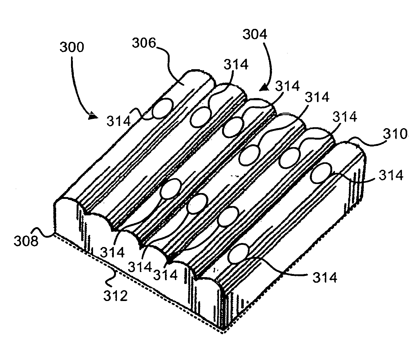
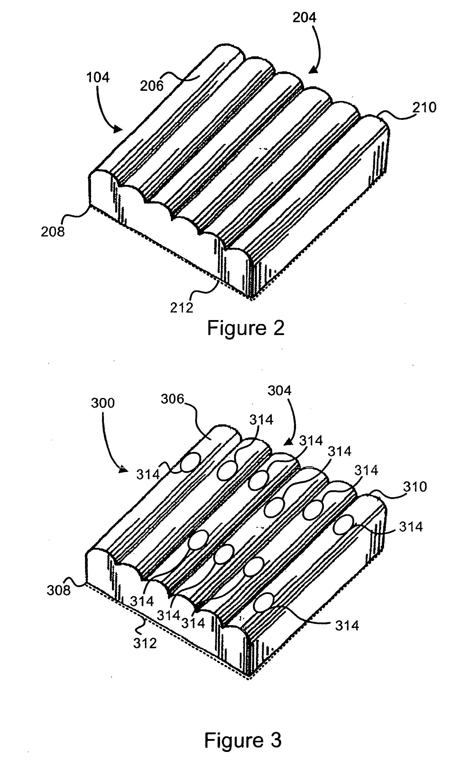
[0064]The microlens window is made from the same material as in Example 1, but the lenticules are parabolic lenses with a shoulder. The total thickness of the microlens window is 5 mils.

example 3

[0065]The microlens window as in either Example 2 or Example 3 is used with a three-dimensional inter-dispersed with a motion (flip) segment.

example 4

[0066]A multi-dimensional piece is designed with clear areas incorporated into the graphical images. Clear areas of different sizes as well as clear areas in a logo are incorporated so there is a discontinuous clear area in all portions of the microlens window. The graphical images are printed on the microlens window as described herein. The graphical image area in non-clear areas is composed of 12 frames. The white opacity area is printed behind all non-clear areas. This product is seen through the “designed in see-through areas.” The advantage is that there exists less alignment in the printing of deeper richer images, thus providing an eye-catching motion and eye-retention three-dimensional images and clear see-through images dispersed through-out the packaging.


PUM

PropertyMeasurementUnit
thicknessaaaaaaaaaa
thicknessaaaaaaaaaa
total thicknessaaaaaaaaaa

Abstract

The method for making a container includes providing a first heated conveyor having a first belt, the first belt including a plurality of heated shoes; providing a second conveyor having a second belt, the first belt and the second belt being substantially overlapping to provide a nip between at least one of the plurality of heated shoes and the second belt, the first and the second belts traveling in a common direction; placing a container on the second belt prior to the nip, the container having a opening disposed therethrough; placing a piece of lenticular material over the opening; and bonding the piece of lenticular material to the opening in the nip.

Description

CROSS-REFERENCE TO RELATED APPLICATIONS[0001]This application is a divisional of U.S. patent application Ser. No. 11 / 730,455, filed Apr. 2, 2007, which claims the benefit of U.S. Provisional Application No. 60 / 778,108, filed Apr. 3, 2006. The entireties of these aforementioned applications are incorporated herein by reference.FIELD OF THE INVENTION[0002]The field of the invention relates generally to packaging and printing. More particularly, the invention relates to microlens windows having interphased images for packaging and printing.BACKGROUND OF THE INVENTION[0003]Today, flat plastic windows exist for paperboard containers. Some marketers of packaged goods use these transparent windows in their packaging to enable a consumer to see the actual product and the level of the product through the window of the packaging. This is done to increase visibility of the actual product that would otherwise be unviewable due to the packaging's non-transparent material of which the packaging o...

Claims


Application Information

Patent Timeline
Patent Type & Authority Applications(United States)
IPC IPC(8): B32B27/08G02B30/27
CPCB31B1/82B31B2201/9076B65D5/4204G02B3/005Y10T156/1084G02B27/2214G09F19/14G09F23/00G02B3/0056B31B50/82G02B30/27G02B27/10B32B27/08
Inventor KARSZES, WILLIAMNIMS, JERRY
Owner NIMS JERRY
Why Eureka
Try Eureka