Display device
a display device and display panel technology, applied in the direction of display/control unit casings, electric apparatus casings/cabinets/drawers, instruments, etc., can solve the problems of device not fitting in the automobile dashboard, the length of the storage cover is also increased, and the device is too large to fit in the dashboard. , to achieve the effect of reducing the number of component members, enhancing commodity value, and reducing cos
- Summary
- Abstract
- Description
- Claims
- Application Information
AI Technical Summary
Benefits of technology
Problems solved by technology
Method used
Image
Examples
second embodiment
[0250]A second embodiment of the present invention will be described. In the second embodiment, a cover is divided into three sections.
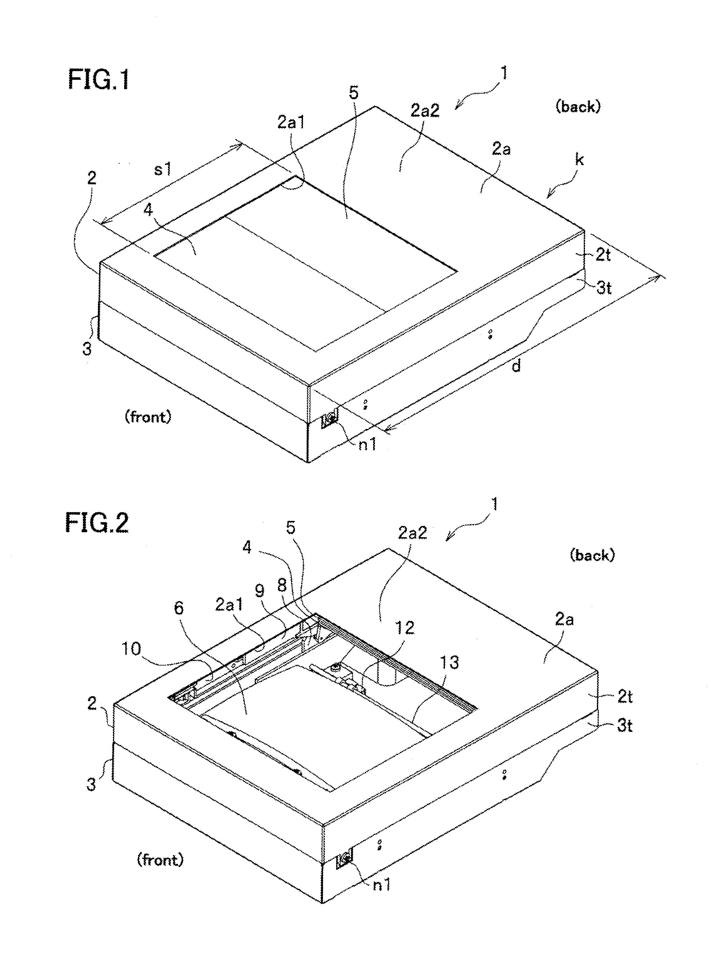
[0251]FIG. 26 perspectively shows a display device 21 according to the second embodiment viewed obliquely from a front upper side, wherein the display device 21 is not in use.
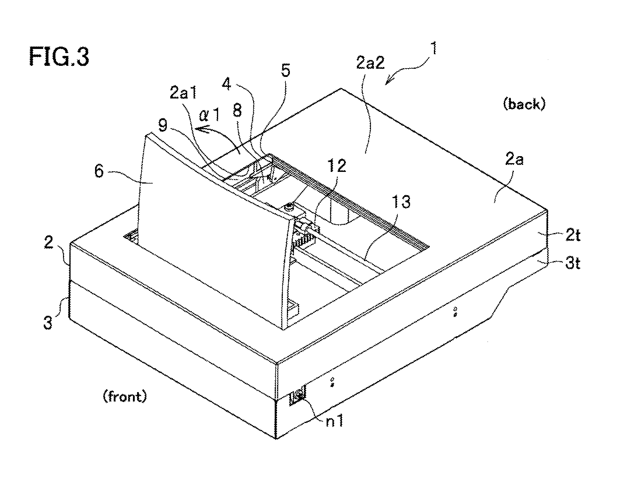
[0252]FIG. 27 perspectively the display device 21 viewed obliquely from the front upper side, wherein the display device 21 is in use such that a combiner 6 raised up.
[0253]In the display device 21, an opening 2a1 is closed by a cover divided into three sections, that is, a first lid 4, a second lid 5 and a third lid (rotary lid member) 22.
[0254]The display device 21 according to the second embodiment is configured the same as the display device 1 according to the first embodiment except that since a part of the opening 2a1 is covered by the third lid 22, the first lid 4 and the second lid 5 are dimensioned smaller, wherein component members having the same or similar configurat...
third embodiment
[0270]A third embodiment of the present invention will be described. In a display device 31 according to the third embodiment, a first lid 4 is retracted immediately below an upper surface plate 2a of an upper case 2, and a second lid 5 is retracted below the first lid 4. Except the configuration described above, the third embodiment has the same configuration as the first embodiment.
[0271]FIG. 31 schematically shows the display device 31 according to the third embodiment viewed from a side, when an opening 2a1 is closed by the first lid 4 and the second lid 5.
[0272]FIG. 32 schematically shows the display device 31 viewed from the side, when the opening 2a1 is opened such that the first lid 4 and the second lid 5 are retracted in the upper case 2.
[0273]FIGS. 33A and 33B schematically show relation between a travel speed of a first cam 8 and a travel speed of a second cam 9, wherein FIG. 33A shows a condition when the opening 2a1 is closed by the first lid 4 and the second lid 5, and...
fourth embodiment
[0292]A fourth embodiment of the present invention will be described. In the fourth embodiment, detection of the rise up position of a combiner 6 is performed by an angle sensor 18, and detection of the retraction position of the combiner 6 is performed by a switch (not shown) unlike in the first embodiment.
[0293]Description will hereinafter be made of the fourth embodiment with reference to FIG. 18.
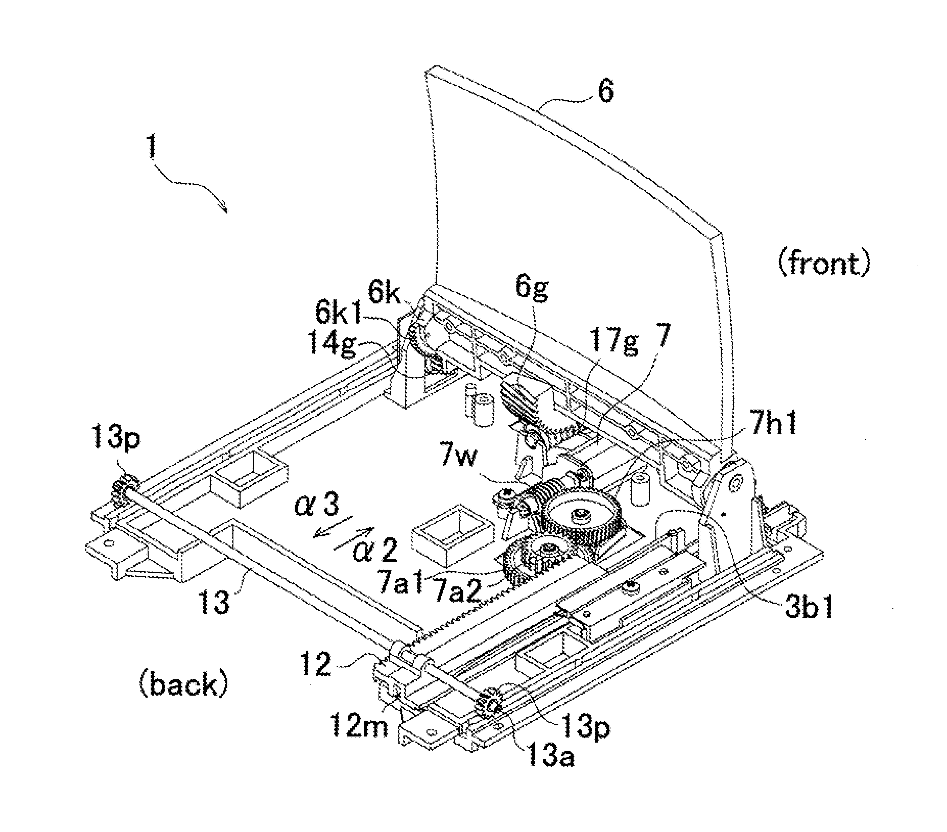
[0294]An angle detection gear member 6k having a partial gear 6k1 is fixed at a combiner support 6s to which the combiner 6 is fixed by a pan head small screw n3.
[0295]When the combiner 6 is retracted and not in use, the partial gear 6k1 of the angle detection gear member 6k of the combiner support 6s is not engaged with an angle detection gear 14g of a rotary circular plate 14.
[0296]When the partial gear 6k1 of the angle detection gear member 6k of the combiner support 6s is out of engagement, a boss 15a of a plate spring 15 is set in a notch 14o formed at the rotary circular plate 14, ...
PUM
 Abstract
Description
Claims
Application Information
 - R&D
- Intellectual Property
- Life Sciences
- Materials
- Tech Scout
- Unparalleled Data Quality
- Higher Quality Content
- 60% Fewer Hallucinations
Browse by: Latest US Patents, China's latest patents, Technical Efficacy Thesaurus, Application Domain, Technology Topic, Popular Technical Reports.
© 2025 PatSnap. All rights reserved.Legal|Privacy policy|Modern Slavery Act Transparency Statement|Sitemap|About US| Contact US: help@patsnap.com


