
Fuel cell system and method for estimating output characteristic of fuel cell

Inactive Publication Date: 2009-03-05
TOYOTA JIDOSHA KK
View PDF8 Cites 18 Cited by
  • Summary
  • Abstract
  • Description
  • Claims
  • Application Information

AI Technical Summary

Benefits of technology

[0006]The present invention improves the accuracy of estimation of an output characteristic of a fuel cell.
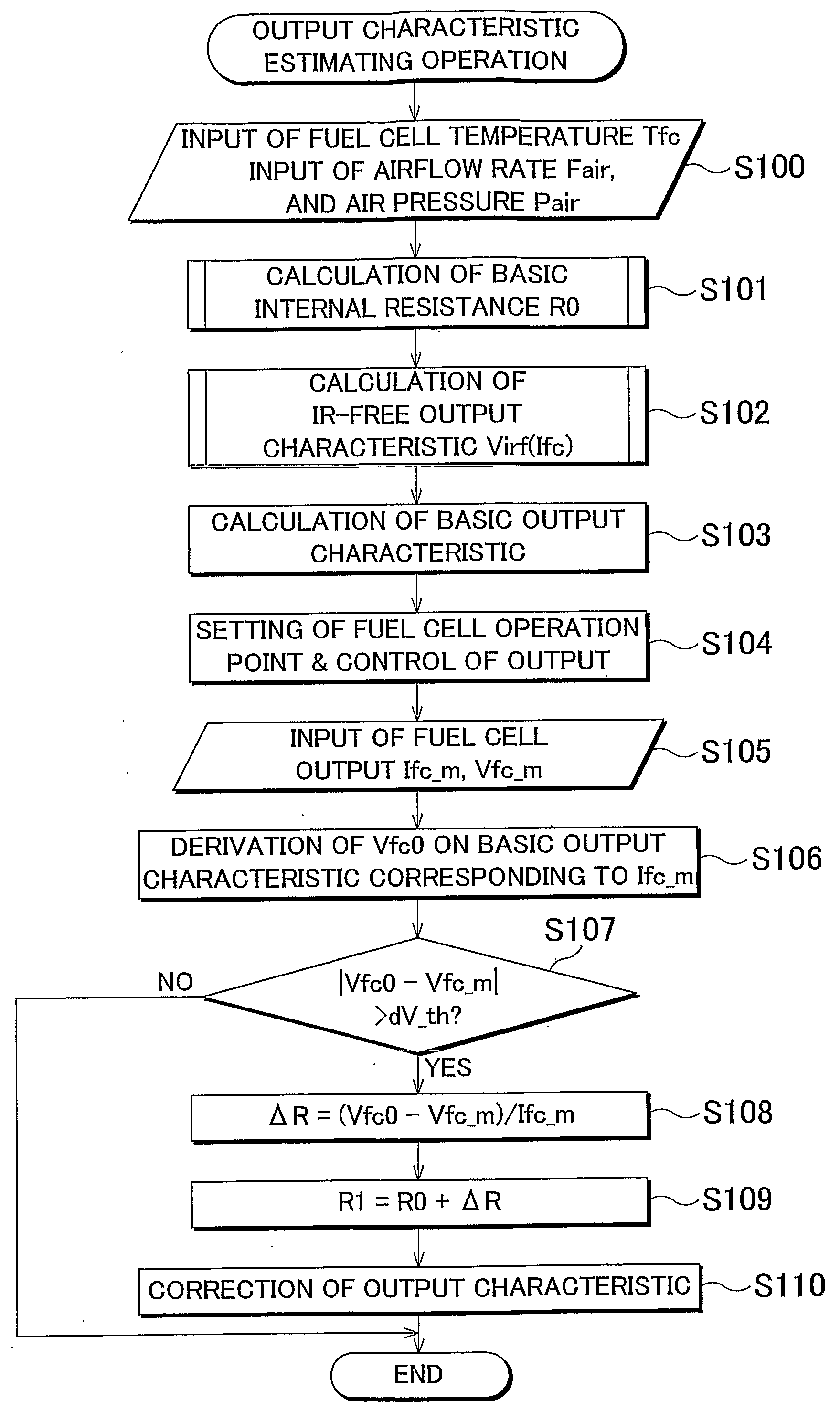
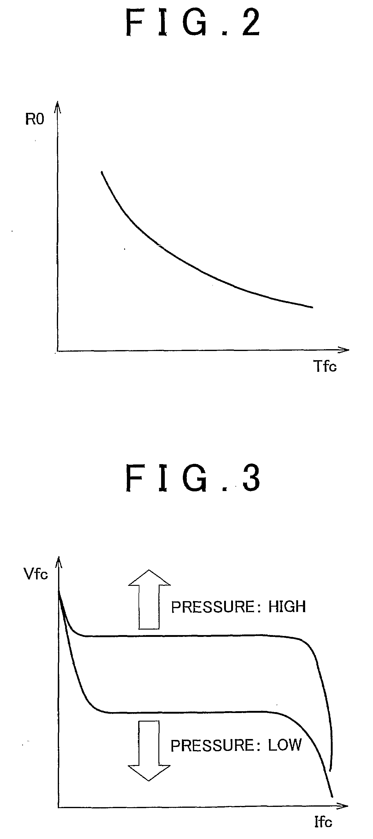
[0008]According to the fuel cell system, the IR-free output characteristic is the relation between output current and output voltage of the fuel cell excluding the influence of the internal resistance at different flow rates and pressures of air supplied to the fuel cell. The IR-free output characteristic is stored together with the flow rate and the pressure. The flow rate and pressure of air to be supplied to the fuel cell is measured and an IR-free output characteristic of the fuel cell is determined based on the measured flow rate and pressure of the air. Therefore, the basic output characteristic of the fuel cell can be estimated accurately, and, consequently, the basic output characteristic can be corrected accurately.
[0010]The calculating unit may have a first correcting unit that corrects the basic internal resistance of the fuel cell based on the output current and the output voltage; and a second correcting unit that corrects the basic output characteristic with the corrected basic internal resistance. According to this configuration, the basic internal resistance of the fuel cell is corrected based on the output current and the output voltage, and the basic output characteristic is corrected. Therefore, the accuracy of the estimation of the basic output characteristic can be improved.
[0011]The calculating unit may further have a correction value storing unit that stores the corrected basic internal resistance as a new basic internal resistance; a third correcting unit that further corrects the basic internal resistance based on the output current and the output voltage when a basic internal resistance has been stored in the storing unit; and a fourth correcting unit that corrects the basic output characteristic with the further corrected basic internal resistance. According to this configuration, the corrected basic internal resistance is stored as a new basic internal resistance, and the basic internal resistance is further corrected based on the output current and the output voltage when a basic internal resistance has been stored in the correction value storing unit. Therefore, the accuracy of the estimation of the basic output characteristic.
[0013]According to this configuration, the impedance measured by the measuring unit and an impedance measured previously and stored in the impedance storing unit are compared. The basic internal resistance is corrected when there is a difference equal to or greater than a predetermined value between the measured impedance and the previously measured impedance. The IR-free output characteristic is corrected when there is not such a difference. Therefore, the object to be corrected can be limited and the accuracy of the correction can be improved.

Problems solved by technology

Therefore, high estimation accuracy cannot necessarily be obtained.

Method used


Image

  • Fuel cell system and method for estimating output characteristic of fuel cell
  • Fuel cell system and method for estimating output characteristic of fuel cell
  • Fuel cell system and method for estimating output characteristic of fuel cell

Examples


first embodiment

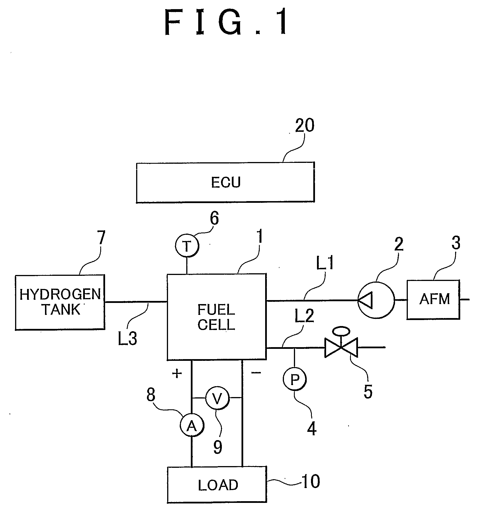
[0037]FIG. 1 is a system configuration diagram of a fuel cell system according to the present invention. The fuel cell system has a fuel cell body 1 including a cell stack in which unit cells are stacked; an air compressor 2 that supplies air to the air electrode side in the fuel cell body 1 through an air supply passage L1; an airflow meter 3 (which may be regarded as a flow rate measuring unit) that measures the flow rate of the air supplied from the air compressor 2 to the fuel cell body 1; a pressure sensor 4 (which may be regarded as a pressure measuring unit) that measures the gas pressure on the air electrode side via a discharge passage L2 on the air electrode side of the fuel cell body 1; a pressure control valve 5 that controls the gas pressure on the air electrode side including the discharge passage L2; a hydrogen tank 7 from which hydrogen is supplied to the hydrogen electrode side in the fuel cell body 1 through a hydrogen supply passage L3; a current sensor 8 (which m...

second embodiment

[0071]FIG. 9 shows a fuel cell system of this embodiment. As compared to the fuel cell system of the second embodiment, the fuel cell system does not have the humidity sensor 12. Also, the fuel cell system has a water vapor exchange membrane type humidifier 13, with a water vapor exchange membrane that humidifies air, instead of the humidifier 11 in FIG. 6. The water vapor exchange membrane type humidifier returns the water vapor (generated water) in the off gas discharged through the discharge passage L2 on the air electrode side to the air supply passage L1 on the upstream side through an exchange membrane therein.

[0072]FIG. 10 shows an example of the relation among the airflow rate Fair in the water vapor exchange membrane type humidifier 13, the temperature Tfc of the fuel cell body 1 and the humidification amount Sair. Here, the airflow rate Fair is the flow rate in the air supply passage L1 on the upstream side.

[0073]In general, the humidification amount Sair increases as the ...

fourth embodiment

[0098]The ECU 20 then measures the AC impedance Zre(ω) of the fuel cell. This step is the same as S301 of the fourth embodiment shown in FIG. 13.

[0099]The ECU 20 then calculates the humidification amount Sair based on the flow rate from the humidity sensor or the humidifier (S210). The ECU 20 then refers a basic internal resistance R0 from the map (see FIG. 14) based on the AC impedance Zre(ω) and the humidification amount. The subsequent steps are the same as those in and after S102 in FIG. 5.

[0100]As described above, in this embodiment, a basic internal resistance R0 is determined from the AC impedance of the fuel cell and the air humidification amount with reference to a map of the relation among the AC impedance, the air humidification amount and the basic internal resistance R0. Therefore, the output characteristic of the fuel cell may be estimated with higher accuracy than in the second embodiment, in which the basic internal resistance R0 is determined simply from the humidif...


PUM


Abstract

A fuel cell system according to the invention includes: a detecting unit (6, 12) that detects an operation parameter of the fuel cell; an internal resistance estimating unit (20) that sets the internal resistance of the fuel cell a basic internal resistance; a flow rate measuring unit (3) that measures the airflow rate; a pressure measuring unit (4) that measures the air pressure; a determining unit (20) that determines the IR-free output characteristic of the fuel cell; a setting unit (20) that sets the basic output characteristic of the fuel cell; an output current measuring unit (8) that measures the output current of the fuel cell; an output voltage measuring unit (9) that measures the output voltage of the fuel cell; and a calculating unit (20) that corrects the basic output characteristic using the output current and the output voltage.

Description

BACKGROUND OF THE INVENTION[0001]1. Field of the Invention[0002]The present invention relates to a fuel cell system and a method for estimating an output characteristic of a fuel cell.[0003]2. Description of the Related Art[0004]In order to improve the power generation efficiency of a fuel cell, a control in which the fuel cell output is determined taking the current-voltage characteristic (which is hereinafter referred to as “output characteristic”) of the fuel cell into account is conventionally performed. However, the current-voltage characteristic changes depending on the conditions of the fuel cell or over time. Thus, a related art is suggested in, for example, JP-A-2002-231295 in which the output characteristic of a fuel cell is estimated from the temperature of the fuel cell, hydrogen pressure or the like and the output of the fuel cell is controlled using the estimated output characteristic to operate the fuel cell efficiently.[0005]In the above related art, however, the out...

Claims


Application Information

Patent Timeline
IPC IPC(8): H01M8/04
CPCB60L11/1881H01M8/04007H01M8/04089H01M8/04126H01M8/0432Y02T90/34H01M8/04492H01M8/04559H01M8/04589H01M8/04634Y02E60/50H01M8/04395B60L58/30Y02T90/40G01R27/00H01M8/04
Inventor WATANABE, NOBUO
Owner TOYOTA JIDOSHA KK
Learn More