
Aerosol Jet (R) printing system for photovoltaic applications

a photovoltaic cell and printing system technology, applied in the direction of dispersed particle separation, separation processes, coatings, etc., can solve the problems of increasing the difficulty of squeegeeing ink through the mesh of the screen, increasing the cost associated with screen waste, and reaching the limit of the approach. , to achieve the effect of reducing the width and thickness of the seed layer

Inactive Publication Date: 2009-03-05
OPTOMEC DESIGN CO
View PDF103 Cites 67 Cited by
  • Summary
  • Abstract
  • Description
  • Claims
  • Application Information

AI Technical Summary

Benefits of technology

[0012]An advantage of the present invention is the ability to reduce the width and thickness of seed layers for collector lines on solar cells.

Problems solved by technology

However, this approach is reaching its limit as the industry pushes for higher efficiency cells and thinner wafers.
However, it becomes increasingly difficult to squeegee the ink through the mesh of the screen as the gap in the stencil is reduced.
Screen stretch also becomes more of a problem, resulting in greater cost associated with screen waste.
While advancements in screen print technology have pushed it beyond what was conventionally thought to be possible a decade ago, the limits to the feature sizes that are possible are rapidly approaching.
Further, as thinner silicon wafers are introduced into production lines, waste due to wafer breakage becomes more significant due to the pressure that screen printing places on the wafer.
However, this high glass concentration increases the resistance and hence the current loss of the collector line.
However, it has several known limitations.
Printing of commercial screen-printing pastes is not possible, necessitating the development of specialized nanoparticle or organometallic inks.
Droplets are relatively large, resulting in line widths that are no better than those achievable by screen-printing.
The gap between the substrate and the print head is critical, resulting in low tolerance to uneven substrates.
Traditional screen print methods do not accommodate these future requirements.

Method used


Image

  • Aerosol Jet (R) printing system for photovoltaic applications
  • Aerosol Jet (R) printing system for photovoltaic applications
  • Aerosol Jet (R) printing system for photovoltaic applications

Examples


Embodiment Construction

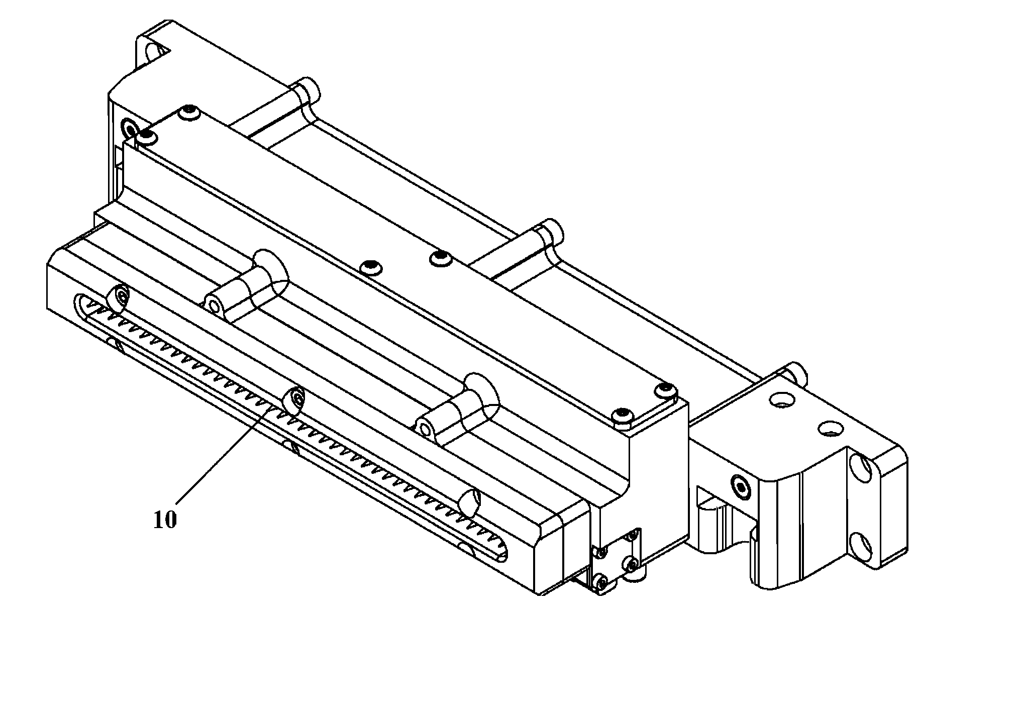
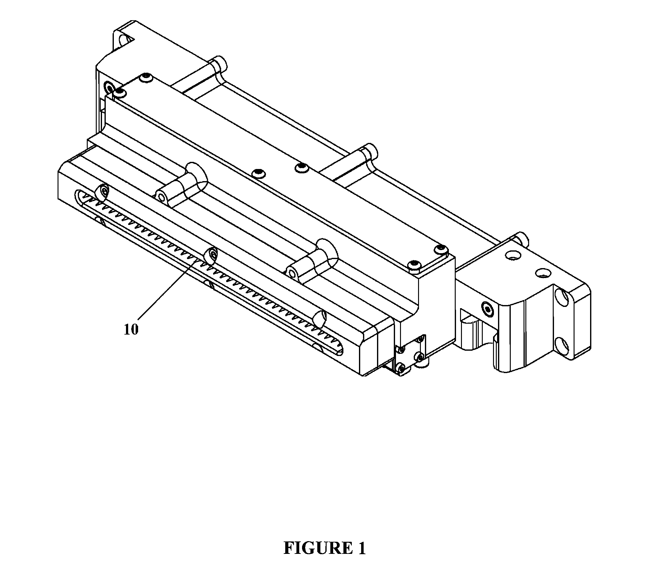
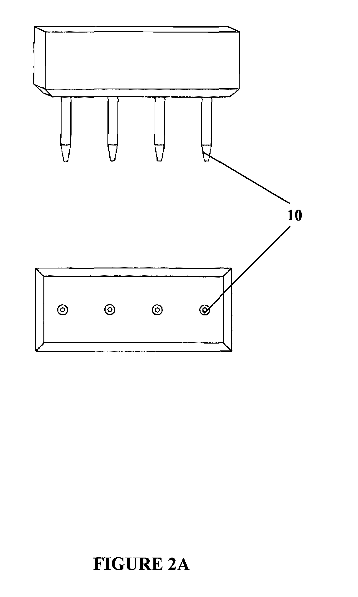
[0025]The present invention generally relates to apparatuses and methods for high-resolution, maskless printing of liquid and liquid-particle suspensions using aerodynamic focusing for metallization applications. In the most commonly used embodiment, an aerosol stream is focused and printed onto a planar or non-planar target, forming a pattern that is thermally or photochemically processed to achieve physical, optical, and / or electrical properties near that of the corresponding bulk material. This process is called M3D® (Maskless Mesoscale Material Deposition) technology, and is used to print aerosolized materials with linewidths that can be an order of magnitude smaller than lines printed with conventional thick film processes. Printing is performed without the use of masks. Further, the M3D® process is capable of defining lines having widths smaller than 1 micron.

[0026]The M3D® apparatus preferably uses an Aerosol Jet® print head to form an annularly propagating jet composed of an...


PUM

PropertyMeasurementUnit
Timeaaaaaaaaaa
Thicknessaaaaaaaaaa
Widthaaaaaaaaaa

Abstract

Method and apparatus for depositing multiple lines on an object, specifically contact and busbar metallization lines on a solar cell. The contact lines are preferably less than 100 microns wide, and all contact lines are preferably deposited in a single pass of the deposition head. There can be multiple rows of nozzles on the deposition head. Multiple materials can be deposited, on top of one another, forming layered structures on the object. Each layer can be less than five microns thick. Alignment of such layers is preferably accomplished without having to deposit oversized alignment features. Multiple atomizers can be used to deposit the multiple materials. The busbar apparatus preferably has multiple nozzles, each of which is sufficiently wide to deposit a busbar in a single pass.

Description

CROSS-REFERENCE TO RELATED APPLICATIONS[0001]This application claims the benefit of the filing of U.S. Provisional Patent Application Ser. No. 60 / 969,467, entitled “Aerosol Jet® Printing System for Photovoltaic Applications”, filed on Aug. 31, 2007, and U.S. Provisional Patent Application Ser. No. 61 / 047,284, entitled “Multi-Material Metallization”, filed on Apr. 23, 2008, the specifications of which are incorporated herein by reference.BACKGROUND OF THE INVENTION[0002]1. Field of the Invention[0003]The present invention relates to the field of direct write printing of metallizations using an integrated system of single and multi-nozzle print heads, particularly directed towards collector lines and busbars for photovoltaic cell production.[0004]2. Description of Related Art[0005]Screen-printing is the most common technique in use today for the front side metallization of crystalline silicon solar cells. However, this approach is reaching its limit as the industry pushes for higher e...

Claims


Application Information

Patent Timeline
IPC IPC(8): B05D5/12B05C5/00
CPCB01D45/08C23C26/00H01L31/022425H01L31/18H05K1/0263H01L2924/0002Y02E10/50H01L2924/00
Inventor KING, BRUCE H.RAMAHI, DAVID H.
Owner OPTOMEC DESIGN CO
Learn More