
Method for manufacturing a nanoporous framework and a nanoporous framework thus produced

a nanoporous framework and nanoporous technology, which is applied in the direction of physical/chemical process catalysts, tin oxides, silicon compounds, etc., can solve the problems of unsuitable many-catalytic application applications, high post-synthetic treatment cost, and low catalyst yield

Inactive Publication Date: 2009-03-05
NANOLOGICA AB
View PDF1 Cites 5 Cited by
  • Summary
  • Abstract
  • Description
  • Claims
  • Application Information

AI Technical Summary

Benefits of technology

[0023]The metal oxide soap precursors are easily and cheaply prepared. Metal soaps have similar self-organizing properties as conventional amphiphlic surfactants.
[0024]The use of self-organizing metal soap reduces the number of steps involved in the production of a metal oxide nanoporous framework. Self-organizing precursors eliminate the need for costly moulds. The cost of impregnation or grafting methods presently used constitutes a main barrier to commercial exploitation of nanoporous materials.

Problems solved by technology

However, despite the high contact area given by the porous framework researchers still have a problem to produce a material giving high catalytic yields at reasonable cost level.
Another problem is that poor hydrothermal stability of the mesoporous silicates produced makes them unsuitable for many catalyst applications.
This method relies on costly post-synthetic treatments of the amorphous silica framework.
This method although potentially universal does not allow for the formation of metal oxide particles within the voids of the pores as evident from the EXFAS, FTIR and catalytic data presented which suggest that at higher loadings of the metal oxide (M:Si=1:5, where M is Ti) the catalyst sites are less active.
These processes usually require expensive alkoxide reactants as metal oxide precursors and yields materials where the loading of metal oxide can not exceed the amount of silica in the material.
A problem with these methods are that the pores get blocked which reduces the surface area of these materials and thus their use as a catalyst.
A problem with post-synthetic depositions of metal oxide particles is that the incorporation of metal oxide centers will not be homogenous and it is very difficult to control the growth of the metal oxide particles.
The internal surface area of the porous material will therefore be reduced and the catalytic activity of such materials is not optimized.
Also, this method involves the use of a costly mold prior to the incorporation step.

Method used


Image

  • Method for manufacturing a nanoporous framework and a nanoporous framework thus produced
  • Method for manufacturing a nanoporous framework and a nanoporous framework thus produced
  • Method for manufacturing a nanoporous framework and a nanoporous framework thus produced

Examples


example 1

[0127]A Gallium Laureate water solution, containing the monodentate soap, was prepared and heated in a closed polypropylene container to 90° C. for 10 hours to induce the complete dissolution of the soap. The pH of the liquor was adjusted to 10 with tetramethyl ammonium hydroxide solution (25% TMAOH in methanol). To this solution tetraethyl orthosilicate was added at 60° C. under constant stirring (300 rpm). A synthesis gel with molar ratio of 1:1000: 4:1 (Gallium Laurate: water: tetramethyl ammonium hydroxide: Tetraethyl orthosilicate) was formed. The synthesis gel was transferred to a Teflon lined stainless steel autoclave and placed in an oven at 120° C. for 24 hours to encourage condensation of the silica, forming the silica / metal soap composite.

[0128]The composite was then heated at 550° C. under flowing oxygen, in order to remove the organic soap, resulting in a porous silicate / gallium oxide composite.

example 2

[0129]A Nickel palmitate water solution, containing the monodentate soap, was prepared and heated in a closed polypropylene container to 90° C. for 10 hours to induce the complete dissolution of the soap. The pH of the clear solution was controlled to 9 by addition of Sodium Hydroxide pellets. To this solution, tetraethyl orthosilicate was slowly added at 80° C. whilst stirring before the resulting synthesis gel was transferred into a Teflon lined stainless steel autoclave and placed in an oven at 120° C. for 24 hours to encourage condensation of the silica, forming the silica / metal soap composite. The synthesis gel had a final molar ratio of 1:1000: 12.5:1 (Nickel Laurate: water: tetramethyl ammonium hydroxide: Tetraethyl orthosilicate). At this stage the silicate / nickel oxide (NiO) composite is green in colour indicating.

[0130]The composite was then heated at 550° C. under flowing oxygen, in order to remove the organic soap, resulting in a black porous silicate / nickel oxide (Ni2O3...

example 3

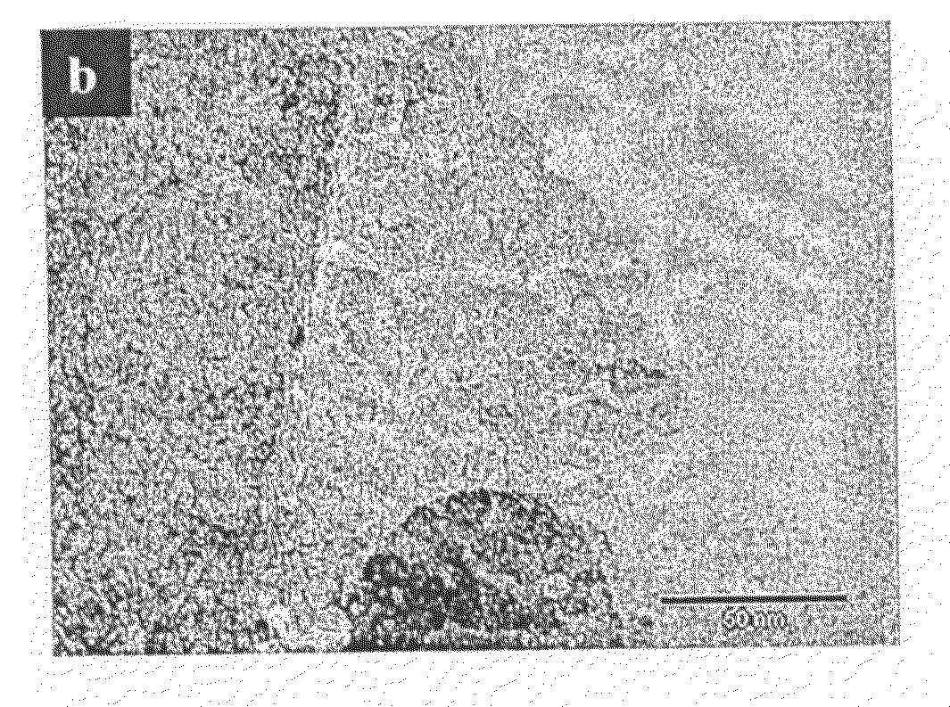
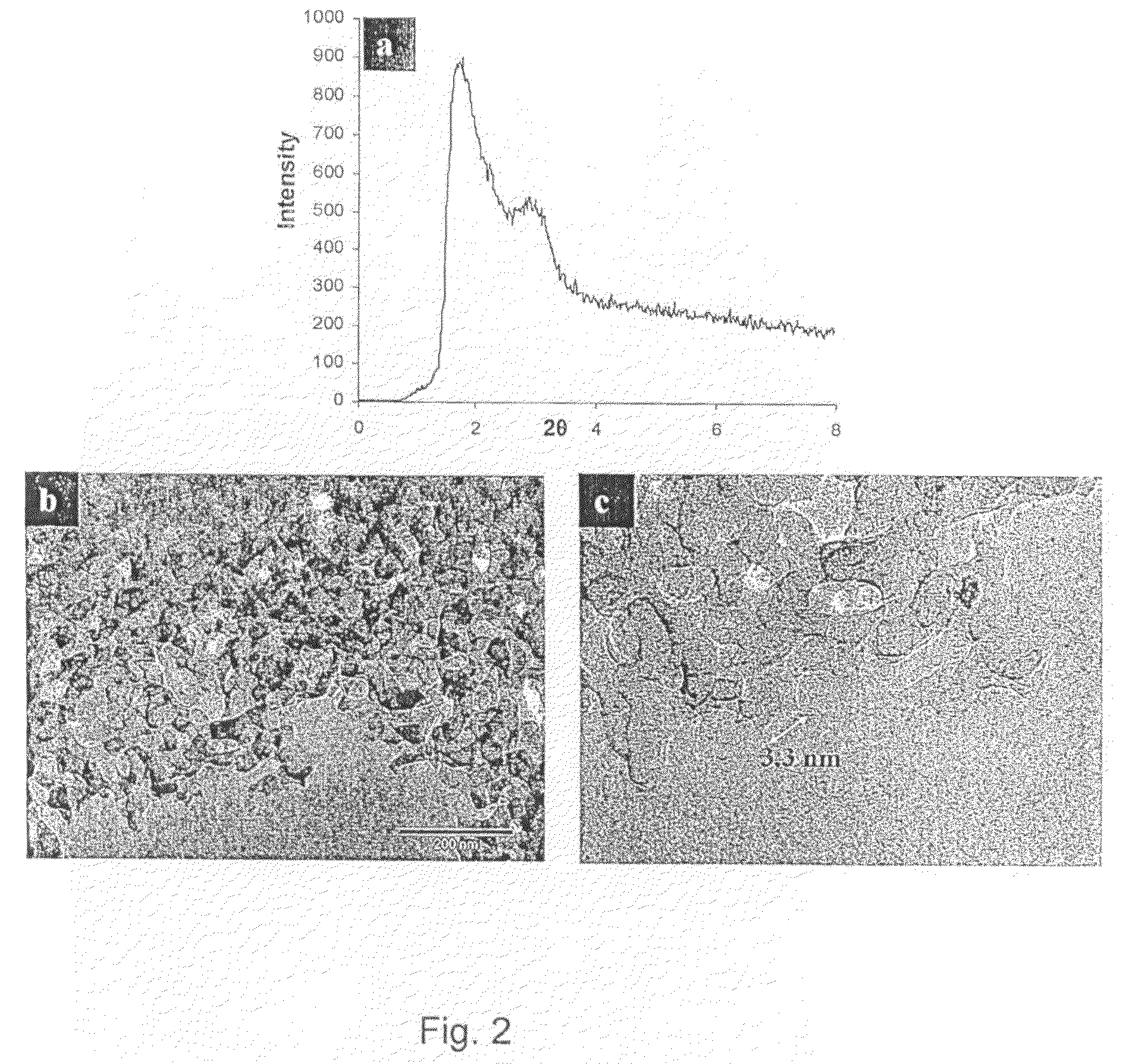
[0132]An Erbium laurate water solution was prepared and warmed in a closed polypropylene container to 70° C. for 10 hours to induce the complete dissolution of the soap. To this solution Trimethyl ammonium hydroxide was added, and the solution was stirred for a further 2 hours. Ammonium propyl silane was added followed by tetraethyl orthosilicate. The synthesis gel had a final molar ratio of 1:1000: 12.5:1 (Erbium Laurate: water: tetramethyl ammonium hydroxide: Tetraethyl orthosilicate). The synthesis gel was treated hydrothermally, at 110° C. for 3 days before it was filtered and dried at RT under static air conditions. The alkyl chains of the soap were removed by calcination at 500° C., under flowing oxygen. The low angle XRD pattern, FIG. 2a, contains an intense diffraction peak owing to ordering at the mesoscale. The wide-angle diffraction intensities arise from the formation of a crystalline metal oxide phase. HRTEM images, FIGS. 2b and c, confirm the porosity of the sample and...


PUM

PropertyMeasurementUnit
thicknessaaaaaaaaaa
temperaturesaaaaaaaaaa

Abstract

The invention concerns a method for manufacturing nanoporous metal oxide or metal active sites frameworks in which the metal oxide precursor is distributed into the framework in the form of a metal soap surfactant.The invention also covers a nanostructure framework comprising metal oxide active sites which are evenly distributed in the framework.

Description

TECHNICAL FIELD[0001]The present invention is directed to a method for manufacturing nanoporous frameworks by incorporating metal oxide active sites into pores of a mesoporous material and nanoporous frameworks materials thus produced.BACKGROUND ART[0002]High surface-area materials with nanoscale dimensions are of special interest in applications where active site mediated chemical reactions play an important role, such as catalytic applications where a high contact area between reactants and catalyst is necessary in order to achieve high yield in a cost-effective manner.[0003]Mesoporous materials offer extremely high contact areas by having porosity by means of nanoporous frameworks. The ordered pore structure and defined pore connectivity of the mesoporous materials make them suitable as nano-reactors to confine growth of nano-materials. The challenge to produce materials with controlled size and shape in nanometer scale has been much advanced the mesoporous and related materials....

Claims


Application Information

Patent Timeline
Patent Type & Authority Applications(United States)
IPC IPC(8): C01B13/14B01J21/00B01J23/00B01J29/00
CPCB01J23/14C01P2006/16B01J35/1061B82Y30/00C01B13/363C01G1/02C01G3/02C01G15/00C01G19/02C01G23/053C01G49/02C01G49/06C01G53/04C01P2002/72C01P2002/85C01P2004/04C01P2004/16C01P2006/12B01J23/755B01J35/647
Inventor GARCIA-BENNET, ALFONSO E.
Owner NANOLOGICA AB
Learn More