
Light emitting unit

Inactive Publication Date: 2009-03-05
TSAI HUA HSIN
View PDF5 Cites 12 Cited by
  • Summary
  • Abstract
  • Description
  • Claims
  • Application Information

AI Technical Summary

Benefits of technology

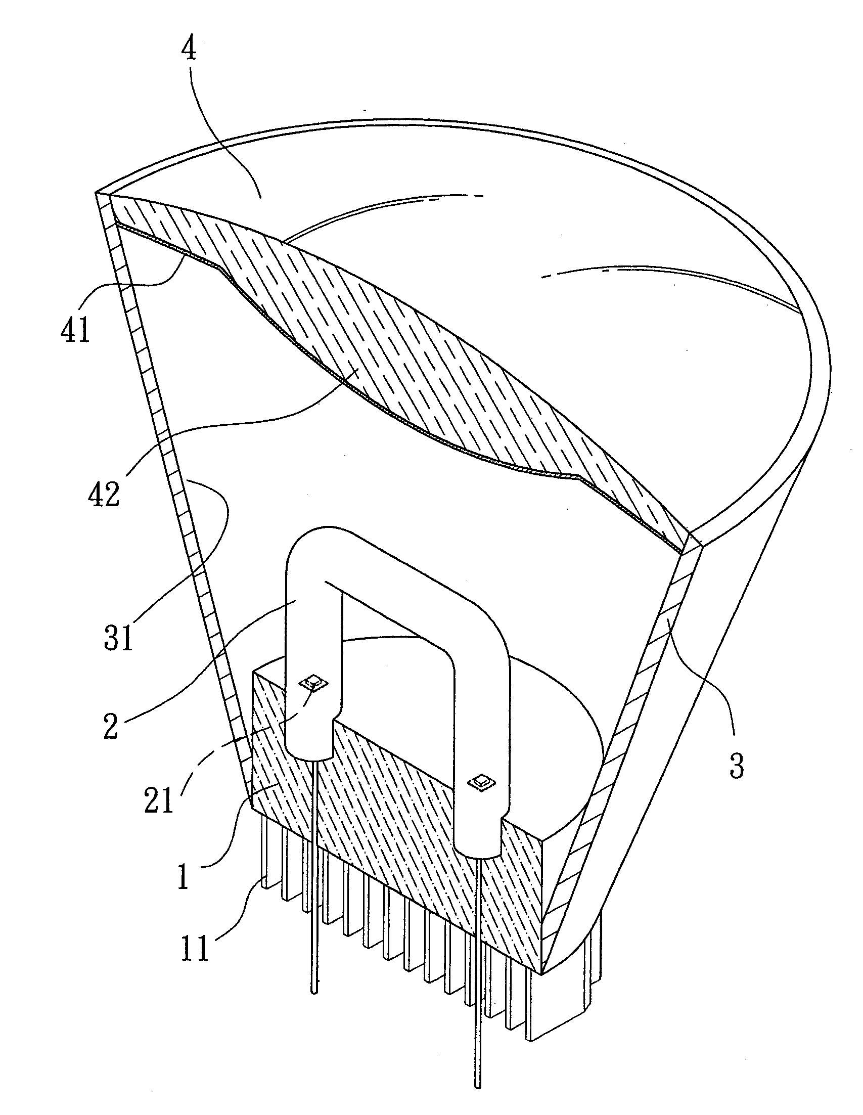
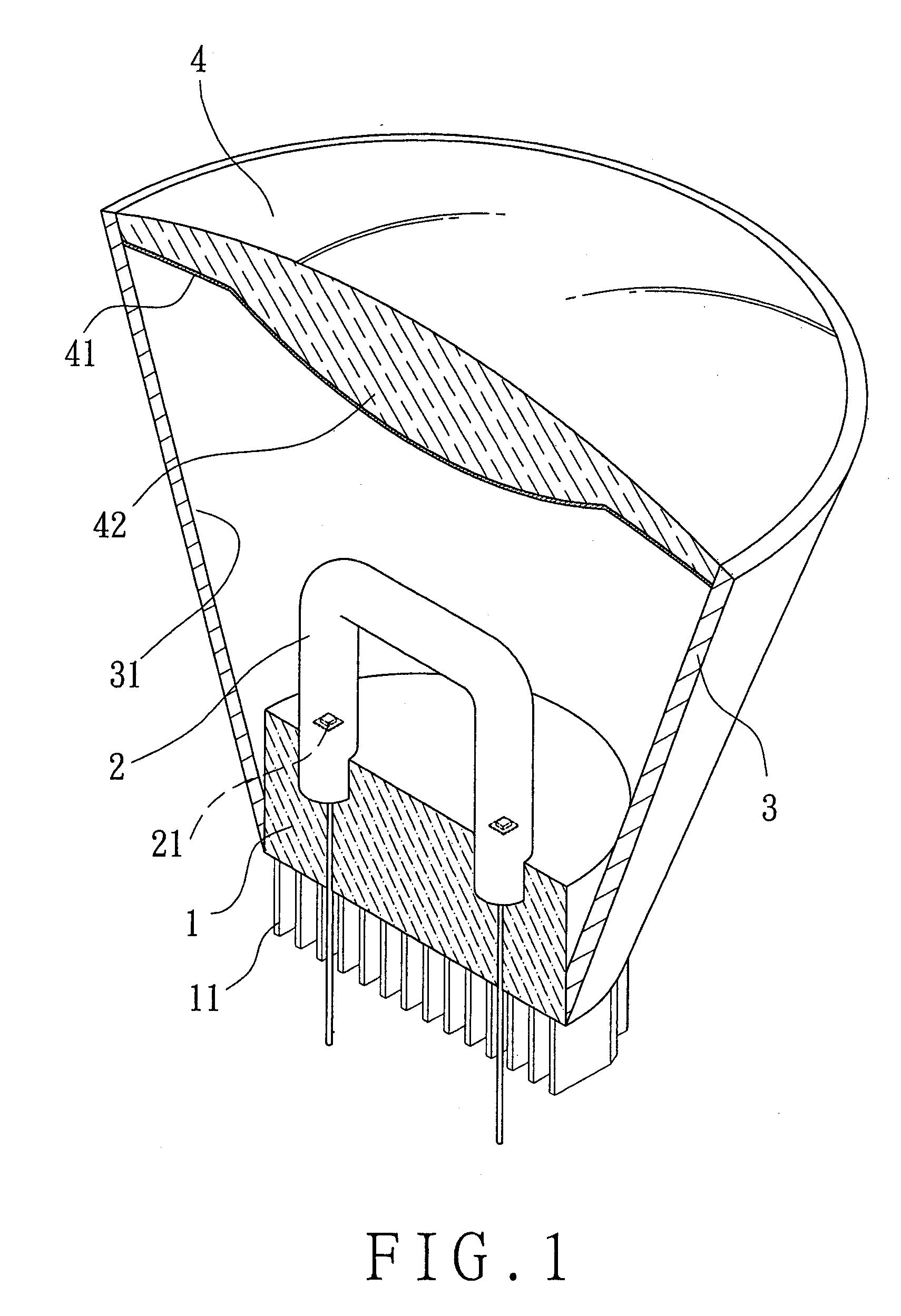
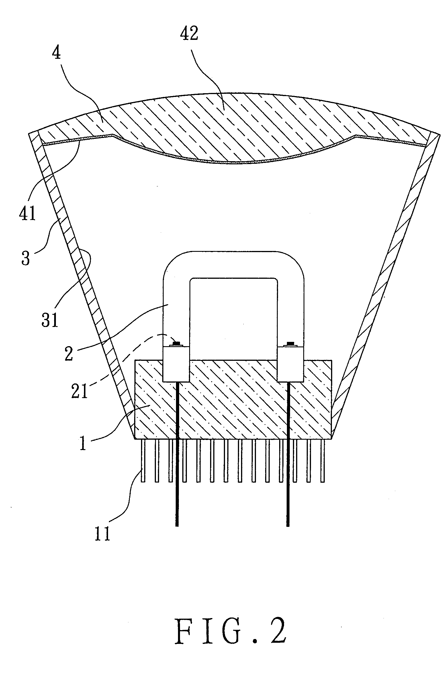
[0007]The light emitting unit of this invention mainly comprises: a lamp holder made of insulating ceramics with high thermal conductivity; a plurality of heat dissipating fins protruding integrally from the outer end face of the lamp holder; a light-transmissive lamp tube provided on the lamp holder; a light source mounted within the light-transmissive lamp tube; a lampshade having a light reflecting surface in the inner edge being provided on the lamp holder with respect to the outer edge of the light-transmissive lamp tube; and a light-transmitting member provided at the outside of the lampshade with respect to the transmissive lamp tube. According to this structure, better illumination effect can be obtained from the entire light emitting unit. Moreover, significant heat dissipation effect can also be achieved by the lamp holder made of insulating ceramics with high thermal conductivity and the heat dissipating fins formed integrally with the lamp holder, such that the reduced service life, light depreciation and burn-down of the inside light source caused by overheating of the light source can be avoided so as to increase the entire performance in use.

Problems solved by technology

While each ordinary light source can emit light to reach intended function of illumination, however it is found in practical application that the key issue of research and development on the light source is generally focused on the improvement of brightness.
On the other hand, the heat dissipation problem of light source is still out of consideration.
Deficiency in proper design of heat dissipation will bring about negative influence on the service lifetime of the light source.
It happens in the case of high power light source that overheating often causes burn-down thereof.

Method used


Image

  • Light emitting unit
  • Light emitting unit
  • Light emitting unit

Examples


Embodiment Construction

[0014]The technical contents of the present invention will become more apparent from the detailed description of the preferred embodiments in conjunction with the accompanying drawings.

[0015]Firstly referring to FIGS. 1 and 2, the light emitting unit of the present invention mainly comprises: a lamp holder (1) made of insulating ceramics with high thermal conductivity; a plurality of heat dissipating fins (11) protruding integrally from the outer end face of the lamp holder (1); a light-transmissive lamp tube (2) provided on the lamp holder (1); a light source (21) mounted in the light-transmissive lamp tube (2), for example a LED or a mercury vapor lamp; a lampshade (3) having a light reflecting surface (31) in the inner edge being provided on the lamp holder with respect to the light-transmissive lamp tube (2); and a light-transmitting member (4) provided at the outer end of the lampshade (3) with respect to the light-transmissive lamp tube (2), which is coated with a fluorescent ...


PUM


Abstract

The light emitting unit of this invention mainly comprises: a lamp holder made of insulating ceramics with high thermal conductivity; a plurality of heat dissipating fins protruding integrally from the outer end face of the lamp holder; a light-transmissive lamp tube provided on the lamp holder; a light source mounted in the light-transmissive lamp tube; a lampshade having a light reflecting surface in the inner edge being provided on the lamp holder corresponding to the light-transmissive lamp tube; and a light-transmitting element, corresponding to the transmissive lamp tube, provided outside the lampshade. According to this structure, significant illumination effect can be obtained from the entire light emitting device. Moreover, good heat dissipation effect can also be achieved by the lamp holder made of insulating ceramics with high thermal conductivity and the heat dissipating fins formed integrally with the lamp holder, such that the reduced service life, light depreciation and burn-out of the inside light source caused by overheating of the light source can be avoided so as to increase the entire performance in use.

Description

BACKGROUND OF THE INVENTION[0001]1. Field of the Invention[0002]The present invention relates to a light emitting unit, particularly to a light emitting unit capable of providing necessary light illumination for user, having good heat dissipation effect such that the reduced service life, light depreciation and burn-down of the inside light source caused by overheating can be avoided so as to increase the entire performance in use.[0003]2. Brief Description of the Prior Art[0004]Various lamps and lanterns for illumination have been developed to enhance task performance or to avoid happening of danger when people conduct a variety of activities in the dark or place with poor illumination. Accompanying with the time changing and the progress of science and technology changing in each passing day, light sources used in increasingly diversified lamps and lanterns, including those that have diversified illumination effect and energy saving efficiency, have been appeared on the market.[00...

Claims


Application Information

Patent Timeline
IPC IPC(8): F21V29/00
CPCF21K9/52F21K9/54F21V3/04F21V29/86F21Y2101/02F21Y2103/025F21V29/74F21V29/004F21K9/61F21K9/62F21Y2103/37F21Y2115/10F21K9/233
Inventor TSAI, HUA-HSIN
Owner TSAI HUA HSIN
Learn More