
Calibration reference light source and calibration system using the same

a reference light source and calibration system technology, applied in the direction of optical radiation measurement, instruments, spectrometry/spectrophotometry/monochromators, etc., can solve the problems of cost and time, unavoidably temperature dependent, and need to be attentive to the changes of a-light sources and filters, etc., to achieve high accuracy and reliability

Inactive Publication Date: 2009-02-26
KONICA MINOLTA SENSING INC
View PDF2 Cites 57 Cited by
  • Summary
  • Abstract
  • Description
  • Claims
  • Application Information

AI Technical Summary

Benefits of technology

[0012]In view of the above situation, an object of the present invention is to provide a low-cost calibration reference light source and a calibration system using the same, which enable a user side to perform sensitivity corrections of spectrophotometers and spectral illuminometers with high accuracy and reliability.
[0013]In a calibration reference light source and a sensitivity calibration system using the same according to the present invention, a plurality of single-wavelength light sources for emitting reference lights having mutually different single-wavelengths are used instead of a black body radiation source for radiating a white light, and not only the intensities of the single-wavelength reference lights, but also the wavelengths thereof are measured to obtain sensitivity correction coefficients of intensity-to-radiance conversion data. Thus, obtained reference radiances are highly reliable and sensitivity correction of spectrophotometers and spectral illuminometers can be performed with high accuracy and reliability at a user side, whereby the calibration reference light source and the calibration system using the same can be obtained at low cost.

Problems solved by technology

Filters, which are normally unavoidably temperature-dependent, are provided in these sensors, and wavelength errors of the filters need to be 0.5 nm or shorter.
Further, attentions need to be paid to changes of the A-light source and the filters with time (e.g. wear damage of a filament in the A-light source).
Thus, it takes cost and time to return and recalibrate and it is difficult to recalibrate at a frequency necessary to maintain the accuracy.

Method used


Image

  • Calibration reference light source and calibration system using the same
  • Calibration reference light source and calibration system using the same
  • Calibration reference light source and calibration system using the same

Examples


first embodiment

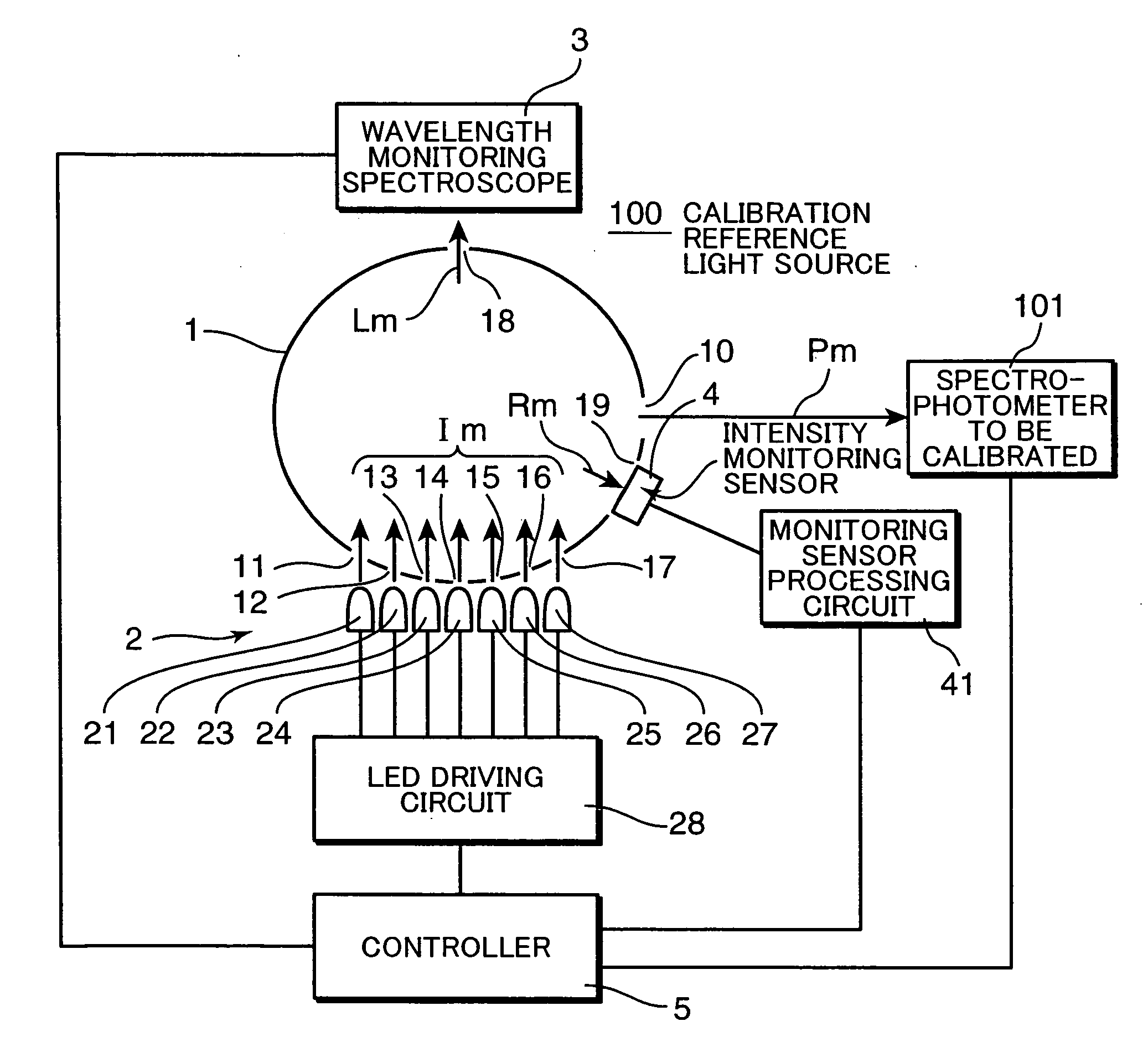
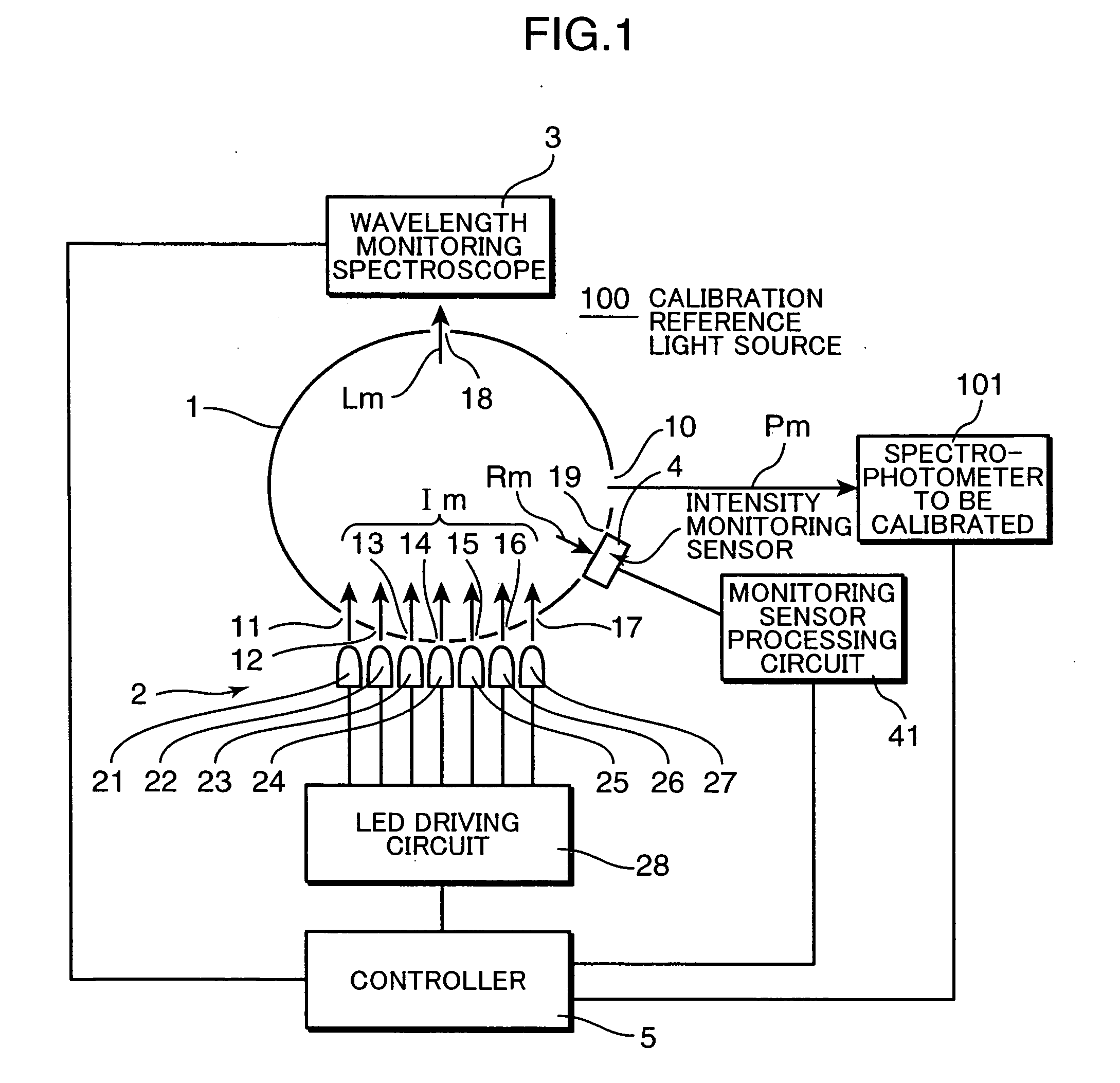
[0024]FIG. 1 is a block diagram showing constructions of a calibration reference light source 100 for a spectrophotometer and a calibration system using the same according to one embodiment. In FIG. 1, the calibration reference light source 100 of this embodiment includes, as main constitute elements, an integrating sphere 1 having an inner wall with a high reflectance and a high diffusivity, a light source unit 2 including light emitting diodes (LEDs) 21 to 27 (hereinafter, LEDm (m=1 to 7)) for emitting single-wavelength lights Im (m=1 to 7) having different wavelengths into the integrating sphere 1 through seven incident openings 11 to 17 formed in the integrating sphere 1, a wavelength monitoring spectroscope 3 to be attached to a wavelength monitoring opening 18 of the integrating sphere 1, an intensity monitoring sensor 4 to be attached to an intensity monitoring opening 19 of the integrating sphere 1 and a controller 5. A polychrometer similar to the polychrometer 210 used in ...


PUM


Abstract

In a calibration reference light source and a sensitivity calibration system using the same, a plurality of single-wavelength light sources for emitting reference lights having mutually different single-wavelengths are used instead of a black body radiation source for radiating a white light, and not only the intensities of the single-wavelength reference lights, but also the wavelengths thereof are measured to obtain sensitivity correction coefficients of intensity-to-radiance conversion data. Thus, obtained reference radiance are highly reliable and sensitivity correction of spectrophotometers and spectral illuminometers can be performed with high accuracy and reliability at a user side, whereby the calibration reference light source and the calibration system using the same can be obtained at low cost.

Description

[0001]This application is based on Japanese Patent Application No. 2007-218791 filed on Aug. 24, 2007, the contents of which are hereby incorporated by reference.BACKGROUND OF THE INVENTION[0002]1. Field of the Invention[0003]The present invention relates to a calibration reference light source and a calibration system using the same, which enable a user side to recalibrate wavelengths and sensitivities of a spectrophotometer and a spectral illuminometer.[0004]2. Description of the Background Art[0005]The spectrophotometer and spectral illuminometer are widely used to measure and evaluate radiances and colors of various light sources and display devices and normally have a construction as shown in FIG. 8. In this spectrophotometer, a light 201 to be measured is gathered by an objective optical system 202 to be incident on an incident slit 211 of a polychrometer 210. The beam incident on the slit forms a wavelength dispersed image of the incident slit 211 on a sensor array 214 via a ...

Claims


Application Information

Patent Timeline
IPC IPC(8): G01J3/02
CPCG01J3/0254G01J3/10G01J2003/2866G01J2003/104G01J3/28
Inventor IMURA, KENJI
Owner KONICA MINOLTA SENSING INC
Learn More