
Permanent Magnet Machine

a permanent magnet machine and magnet technology, applied in the direction of magnetic circuit rotating parts, magnetic circuit shapes/forms/construction, electric devices, etc., can solve the problem of dissipation of part of the vehicle kinetic energy, and achieve the effect of improving overall performance, improving the performance of the motor-generator, and degrading the generating mode performan

Active Publication Date: 2009-02-19
FORD GLOBAL TECH LLC
View PDF24 Cites 43 Cited by
  • Summary
  • Abstract
  • Description
  • Claims
  • Application Information

AI Technical Summary

Benefits of technology

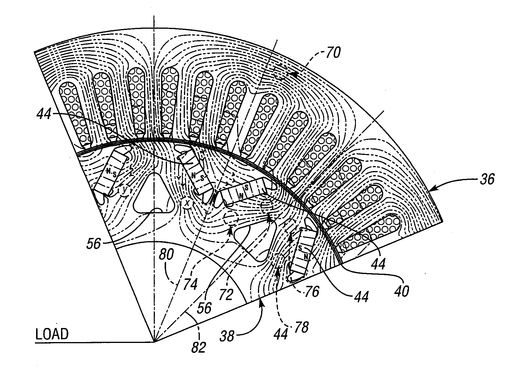
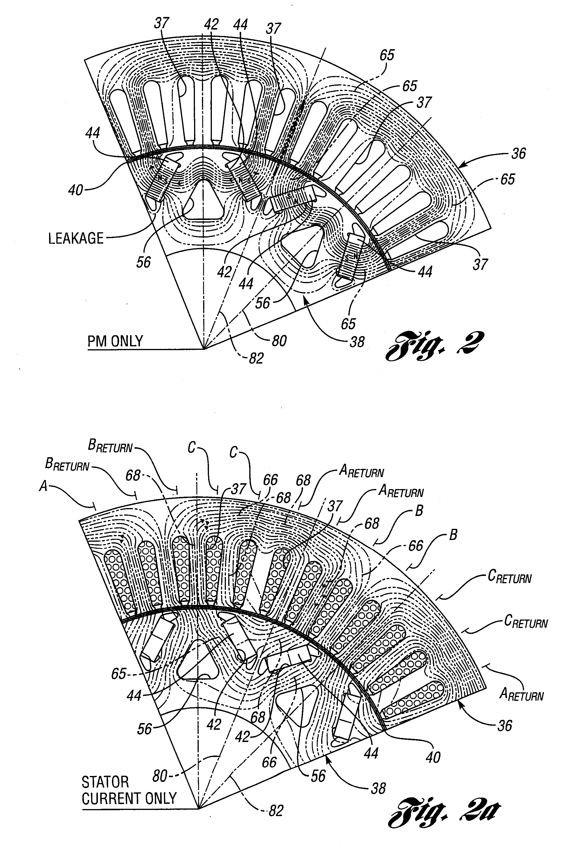
[0012]Because of this asymmetric operating characteristic of hybrid electric vehicle powertrains, a permanent magnet machine embodying features of the present invention is adapted for use in both a parallel hybrid electric vehicle powertrain and a series hybrid electric vehicle powertrain. The asymmetric disposition of elements of a rotor having the features of the invention will result in an improvement in the electromagnetic performance of the permanent magnet machine during motoring although its electromagnetic performance may be degraded during operation in the generating mode. But, since the permanent magnet machine operates in a motoring mode during a larger percentage of its total operating time, improved performance of the permanent magnet machine during motoring is far more significant to its overall performance than the degradation in performance during its operation in a generating mode.
[0014]Since a motoring operating mode is predominant for a permanent magnet machine in a hybrid electric vehicle powertrain, as explained above, the location and shape of the oil holes can be tailored to optimize the operation of the permanent magnet machine in a motoring mode, thereby improving overall performance. A strategic location, size and shape of the oil holes thus can improve the performance of the motor-generator in the motoring mode, while somewhat degrading performance in the generating mode. The different torque requirements for a motoring mode and a generating mode make it possible to design the rotor with an asymmetric geometry that will take full advantage of the predominant magnetic flux distribution path.
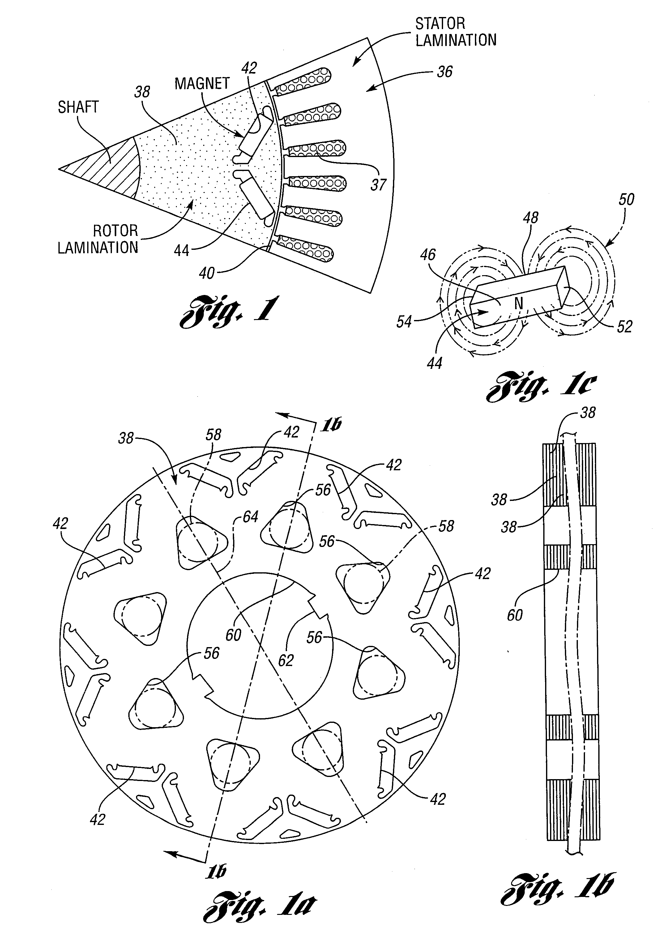
[0016]In the disclosed embodiments of the invention, the oil holes can be generally triangular rather than round. A strategic location of the oil holes, furthermore, will optimize the flux distribution for improved electromagnetic performance during motoring. The position of the oil holes relative to the magnets is asymmetric. This asymmetry can be achieved by angularly displacing the oil holes relative to axes of symmetry that contain the geometric centers of the oil holes or by displacing the oil holes sideways relative to their axes of symmetry.
[0017]According to another embodiment of the invention, an asymmetric rotor design can be achieved by locating the magnets, rather than the oil holes, in an asymmetric fashion so that the position of the oil holes becomes optimum relative to the magnets.
[0018]According to yet another embodiment of the invention, asymmetrically positioned extra holes or cavities may be provided in the rotor in proximity to the magnets to increase electromagnetic torque produced by the machine.

Problems solved by technology

During operation of the permanent magnet machine in a generating mode as the vehicle is braking, however, only a part of the vehicle kinetic energy is dissipated through mechanical brakes and engine braking.
But, since the permanent magnet machine operates in a motoring mode during a larger percentage of its total operating time, improved performance of the permanent magnet machine during motoring is far more significant to its overall performance than the degradation in performance during its operation in a generating mode.

Method used


Image

  • Permanent Magnet Machine
  • Permanent Magnet Machine
  • Permanent Magnet Machine

Examples


Embodiment Construction

[0040]For the purpose of describing an operating environment for the permanent magnet machine of the invention, reference first will be made to FIGS. 14, 15 and 16, which respectively illustrate a series-parallel hybrid electric vehicle powertrain, a split-power hybrid electric vehicle powertrain and a series hybrid electric vehicle powertrain. In the case of the powertrain schematically illustrated in FIG. 16, an engine 10 is mechanically connected to a generator 12, which in turn is electrically coupled to an electric motor 14. Typically, the electrical coupling includes a DC link comprising an AC / DC converter 16 and a DC / AC converter 16′. A high-voltage traction battery 18 is coupled to the DC link through a DC / DC converter 20. The motor is mechanically coupled to a geared transmission mechanism 22, which may have multiple-ratio gearing or a single-ratio gearing.

[0041]Traction wheels 24 are driven by torque output elements of the transmission mechanism. All of the mechanical ener...


PUM


Abstract

A permanent magnet electric machine with optimum motoring efficiency is disclosed. It is adapted for use in a hybrid electric vehicle powertrain. An asymmetric magnetic flux distribution pattern in the rotor of the machine is established to improve operating efficiency of the machine when it is in a motoring mode.

Description

BACKGROUND OF THE INVENTION[0001]1. Field of the Invention[0002]The invention relates to a permanent magnet machine with an asymmetric rotor design.[0003]2. Background Art[0004]A permanent magnet electric machine typically has a rotor comprising a ferrous metal core and embedded sets of permanent magnets. A stator, which surrounds the rotor, is comprised of a ferrous metal and windings with alternating currents. Such machines, which sometimes are referred to as interior permanent magnet machines, are capable of functioning as a motor or as a generator. The sets of magnets are inserted in holes or cavities in the rotor core.[0005]The weight of the rotor and the moment of inertia of the rotor can be reduced by providing channels in the rotor core. The channels are also used for accommodating cooling oil flow for heat dissipation for some applications. These channels or “oil holes” typically are located symmetrically adjacent rotor magnetic poles for the permanent magnets. The permanen...

Claims


Application Information

Patent Timeline
IPC IPC(8): H02K1/27H02K21/14B60L50/16
CPCH02K1/2766Y02T10/642B60L1/02B60L3/0061B60L7/14B60L11/123B60L11/14B60L15/2009B60L2210/10B60L2210/40B60L2220/14B60L2240/36B60L2240/421B60L2240/423B60L2240/441B60L2240/443Y02T10/7077Y02T10/7241Y02T10/7275Y02T10/7216Y02T10/6217Y02T10/641B60L50/61B60L50/16Y02T10/62Y02T10/64Y02T10/72Y02T10/7072Y02T10/70H02K1/20H02K1/32H02K1/274
Inventor LIANG, FENGDEGNER, MICHAEL W.MUNOZ, ALFREDO R.
Owner FORD GLOBAL TECH LLC
Learn More