
Thermoplastic Resin Foam

a technology of thermoplastic resin and foam, applied in the field of thermoplastic resin foam, can solve the problems of increasing the light leakage to the backside of the film, the film per se will not have shape-retention properties, etc., and achieve the effect of reducing the thickness of the sheet and high light reflectance ratio

Inactive Publication Date: 2009-02-12
FURUKAWA ELECTRIC CO LTD
View PDF1 Cites 15 Cited by
  • Summary
  • Abstract
  • Description
  • Claims
  • Application Information

AI Technical Summary

Benefits of technology

[0009]The present invention has been accomplished in view of the foregoing, and an object of the invention is to provide a thermoplastic resin foam having high reflectance ratio and shape-holding properties.
[0012]Since the mean bubble diameter of the thermoplastic according to the present invention is fine, 10 μm or less, the reflectance ratio of light is high, the thickness of the sheet can be reduced, and the foam can be suitably used as a light-reflecting plate.

Problems solved by technology

However, since extension processing is performed on the unextended film, the thickness of the obtained film becomes thin, less than 200 μm, and, therefore, the film per se will not have shape-retention properties and the light leaking to the backside of the film will also increase.

Method used


Image

  • Thermoplastic Resin Foam
  • Thermoplastic Resin Foam

Examples


example 1

[0034]After 2 parts by weight of zinc oxide with a mean particle diameter of 500 nm were added to polyethylene terephthalate (grade: SA-1206, manufactured by UNITIKA. LTD.) and kneaded, the resin was formed into a 0.30 mm thick×300 mm wide×60 mm long sheet. This polyethylene terephthalate sheet and a separator (grade: FT300, manufactured by Japan Vilene Company, Ltd.) of 160 μm thick×290 mm wide×60 mm long olefin system non-woven cloth with nominal weight of 55 g / m2 were stacked and rolled to form a roll such that there are no parts wherein the surfaces of polyethylene terephthalate come into contact with each other.

[0035]Afterwards, the roll was placed within a pressure vessel, the vessel was pressurized to 6 Mpa with carbon dioxide gas, and the carbon dioxide gas was allowed to permeate the polyethylene terephthalate sheet. The permeation time of the carbon dioxide gas to the polyethylene terephthalate sheet was 72 hours.

[0036]Next, the roll was removed from the pressure vessel, a...

example 2

[0038]After 2 parts by weight of zinc oxide with a mean particle diameter of 200 nm were added to polyethylene terephthalate (grade: SA-1206, manufactured by UNITIKA. LTD.) and kneaded, the resin was formed into a 0.33 mm thick×300 mm wide×60 mm long sheet. Aside from this, the same conditions as in Example 1 were set. The obtained foam was uniformly foamed and very fine, the mean bubble diameter being 4.1 μm. Although the thickness of the foam was thin, 500 μm, the reflectance ratio of the foam sheet showed an extremely high value of 99%.

example 3

[0039]The same conditions as in Example 2 were set, aside from the quantity of zinc oxide added being 3 parts by weight. The obtained foam was uniformly foamed and very fine, the mean bubble diameter being 3.4 μm. Although the thickness of the foam was thin, 500 μm, the reflectance ratio of the foam sheet showed an extremely high value of 98%.


PUM

PropertyMeasurementUnit
diameteraaaaaaaaaa
thicknessaaaaaaaaaa
diameteraaaaaaaaaa

Abstract

A thermoplastic resin sheet which has both a high reflectance ratio and excellent shape-holding property suitable for backlights and illumination boxes for use in illumination signboards, illumination fixtures and displays and illumination boxes. The thermoplastic resin foam is manufactured by a manufacturing method including a process for containing inert gas by holding thermoplastic resin sheet containing metallic oxide in a pressurized inert gas atmosphere and a process for heating the thermoplastic resin sheet in which the inert gas is contained at a temperature higher than the softening temperature of the thermoplastic resin, under normal pressure, and foaming the resin.

Description

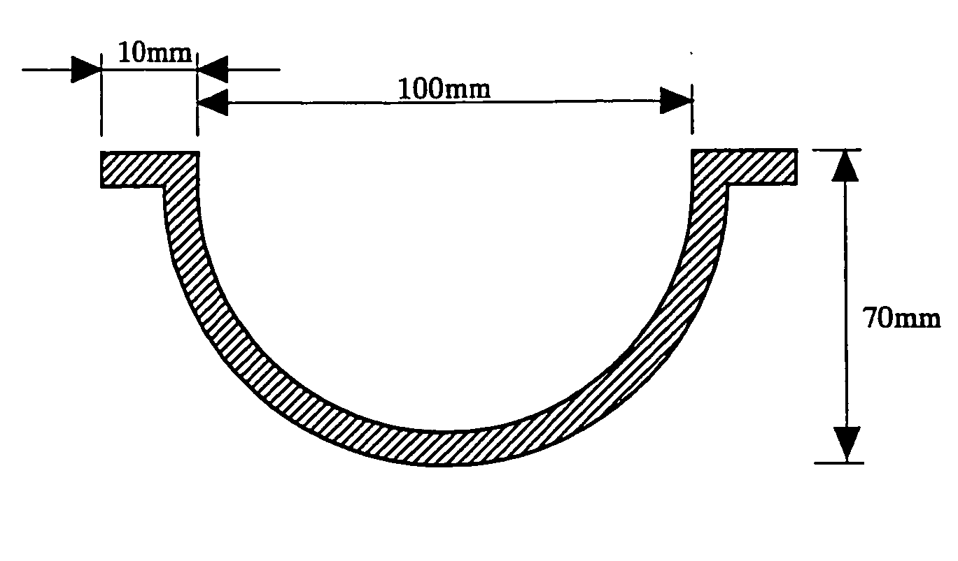
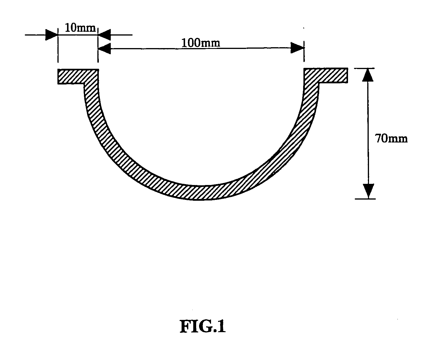
TECHNICAL FIELD[0001]The present invention relates to thermoplastic resin foam. More particularly, the present invention relates to thermoplastic resin foam having fine pores with mean bubble diameter of 10 μm or less within. Since the thermoplastic resin foam obtained according to the present invention has high optical reflectance ratio, the foam can be suitably used in backlights and illumination boxes for illumination signboards, lighting fixtures, displays, and the like.BACKGROUND ART[0002]Conventionally proposed light reflector plates for use in backlights for illumination signboards, lighting fixtures, displays, and the like, include those fabricated such that a light-reflecting synthetic resin film or sheet is formed into a three-dimensional shape to thereby yield a light reflector plate (refer to, for example, Patent Reference 1).[0003]Known light-reflecting synthetic resin foam film or sheet include synthetic resin film or sheet having numerous fine bubbles or pores within ...

Claims


Application Information

Patent Timeline
Patent Type & Authority Applications(United States)
IPC IPC(8): C08J9/00
CPCB29C44/3446B29C44/3453C08J2367/00C08J9/122C08J2201/032C08J9/0066C08J9/12C08J9/22C08K3/22
Inventor MASUDA, KOHJIITO, MASAYASUYOSHIDA, NAOKI
Owner FURUKAWA ELECTRIC CO LTD
Learn More