
Image pickup device-equipped rear-view mirror

a technology of rear-view mirror and pickup device, which is applied in the direction of television system, instruments, transportation and packaging, etc., can solve the problems of obstructing the driver's safe driving, difficult to provide both a reflectance, and driver's feeling, so as to reduce the reflected light strength, reduce the dependence on the view angle, and reduce the effect of glare prevention

Active Publication Date: 2009-02-12
MURAKAMI CORP
View PDF14 Cites 145 Cited by
  • Summary
  • Abstract
  • Description
  • Claims
  • Application Information

AI Technical Summary

Benefits of technology

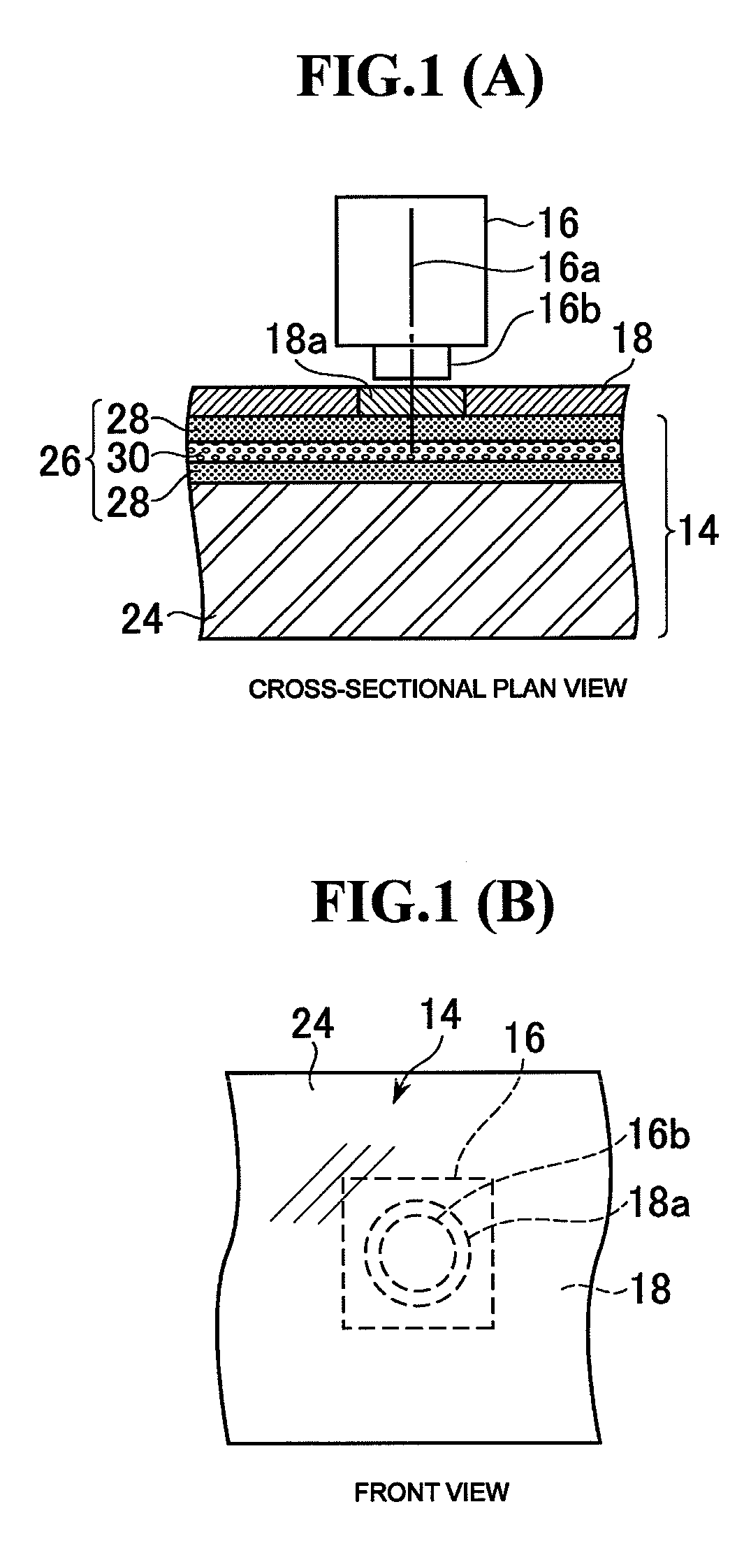
[0009]According to this aspect of the present invention, since the mirror element has an integrating sphere reflectance of 40 to 60% in the visible range, a reflectance that meets the laws and regulations for a vehicle mirror can be obtained and in addition, glare like a cold mirror gives will not be given to drivers, so it is suitable for safe driving. Also, although the mirror element has transmission property because it has an integrating sphere reflectance of 40% to 60% in the visible range, a dark color mask member is arranged behind the mirror element, and consequently, the inside of the mirror cannot be seen through, which provide an improved appearance (design). Also, the near-infrared transmittance of the mirror element is no less than 70% for the whole or part of the band belonging to the near-infrared range within the entire sensitive wavelength range of the near-infrared camera, and the near-infrared transmittance of at least a region of the dark color mask member where the near-infrared camera is arranged is no less than 70% for the whole or part of the band belonging to the near-infrared range within the entire sensitive wavelength range of the near-infrared camera, and the band for which the near-infrared transmittance of the mirror element is no less than 70%, and the band for which the near-infrared transmittance of the dark color mask member is no less than 70% have a band where they overlap each other, making it possible to perform sufficient image pickup by means of the near-infrared camera.
[0011]This aspect of the present invention further comprises a near-infrared lamp arranged behind the dark color mask member, and makes it possible that near-infrared light emitted from the near-infrared lamp is transmitted through the region of the dark color mask member with a near-infrared transmittance of no less than 70% and the mirror element, and released from a front surface of the mirror element. Accordingly, it is possible to pick up an image of an image pickup target by means of illumination by the near-infrared lamp even at night.
[0012]This aspect of the present invention makes it possible that a visible-range reflection peak wavelength of the mirror element is 500 nm to 550 nm. Accordingly, the effect of reducing the reflected light strength for both bluish short wavelength range light from a discharge lamp and a reddish long wavelength range light from a halogen lamp can be obtained while the reflectance that meets the laws and regulations for a vehicle mirror is ensured, making it possible to obtain a higher glare prevention effect.
[0014]This aspect of the present invention makes it possible that a hydrophilic functional layer containing a photocatalytic substance is formed on the front surface of the mirror element. Alternatively, the present invention makes it possible that a laminated film including a photocatalytic layer and a hydrophilic layer is formed on the front surface of the mirror element. Accordingly, a favorable vision can be ensured even in the rain.

Problems solved by technology

According to a rear-view mirror using a half mirror, which is disclosed in Japanese Patent Laid-Open No. 5-294183, Japanese Patent Laid-Open No. 7-186831 and Japanese Patent Laid-Open No. 2000-264128, since the transmittance and the reflectance of a half mirror are incompatible with each other, it has been difficult to provide both a reflectance that meets the laws and regulations as a vehicle mirror and a transmittance for obtaining a sufficient image by means of an image pickup element.
Also, according to a rear-view mirror using a cold mirror, which is disclosed in Japanese Patent Laid-Open No. 2000-264128, since a cold mirror has a reflectance close to 100% in the visible range, there is a problem in that headlight from behind makes a driver have the feeling of glare at night, obstructing the driver's safe driving.
Furthermore, since a cold mirror has a large view angle dependency, the inside of the mirror may be seen through or a discontinuous part may arise in the tone of reflected light, depending on the position of the driver's viewpoint, and thus, there is also a problem of appearance (design).
A rear-view mirror having a mirror element with its reflecting film removed at a part thereof, which is disclosed in Japanese Patent Laid-Open No. 2000-236468, has a problem in that the backward visibility may deteriorate since a part of the mirror element does not function as a mirror.
Also, the mirror element with a part of its reflecting film removed has a problem of appearance (design).

Method used


Image

  • Image pickup device-equipped rear-view mirror
  • Image pickup device-equipped rear-view mirror
  • Image pickup device-equipped rear-view mirror

Examples


Embodiment Construction

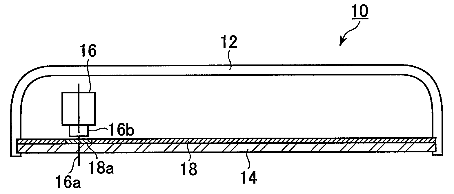
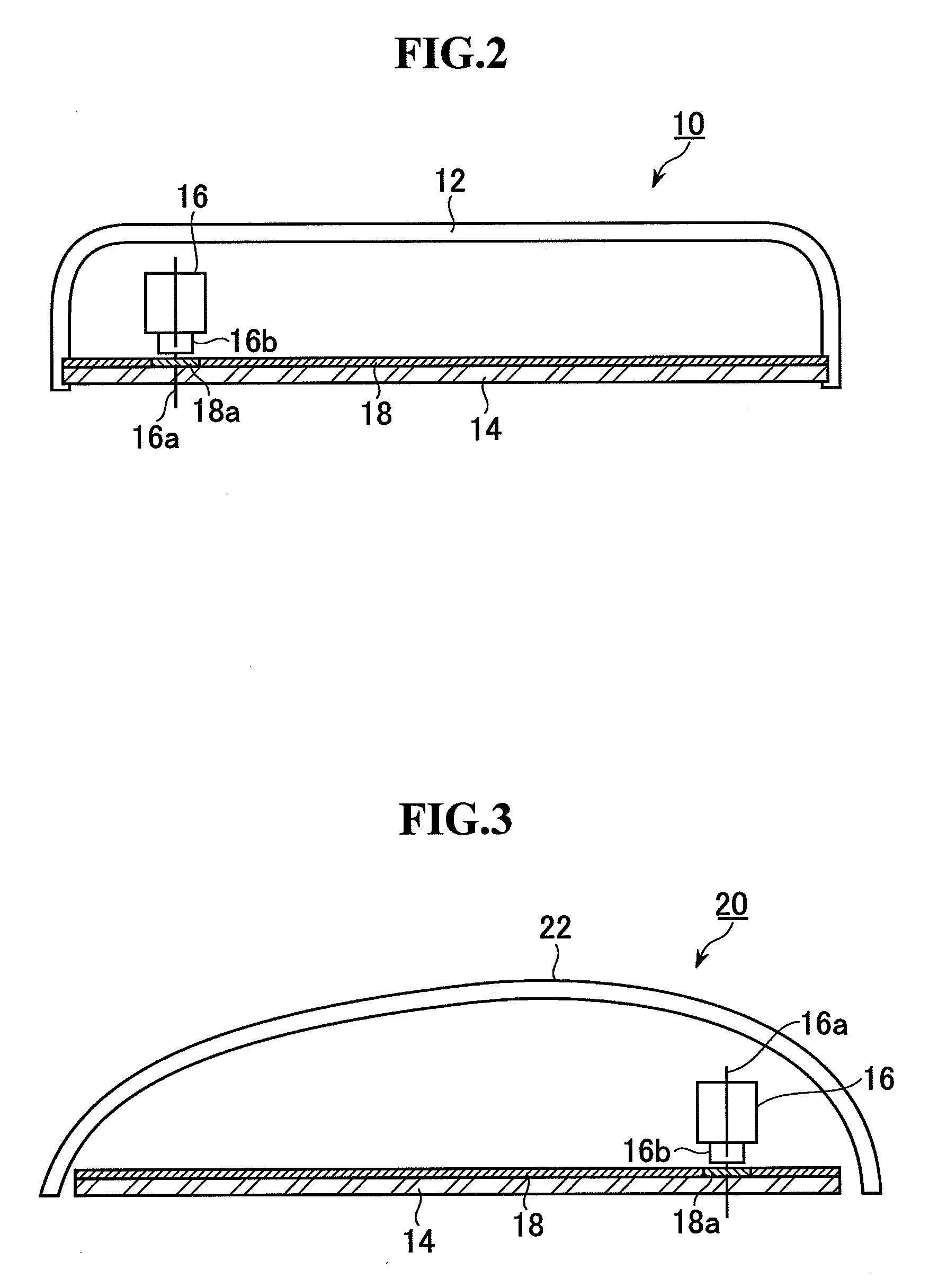
[0028]An embodiment of the present invention will be described below. FIGS. 2 and 3 each show an overview of an inner structure of a vehicle mirror in which the present invention is employed. FIG. 2 shows an inner mirror, and FIG. 3 shows an outer mirror. Each of the Figures is a cross-sectional plane view of a housing and a mirror element. In FIG. 2, an inner mirror 10 has a mirror element 14 attached to a front opening of a housing 12. The mirror element 14 has an integrating sphere reflectance of 40% to 60% in the visible range, and its near-infrared transmittance is set to no less than 70% for the whole or part of the band belonging to the near-infrared range within the entire sensitive wavelength range of a near-infrared camera 16, which will be described later. Also, the visible-range reflection peak wavelength of the mirror element 14 is 500 nm to 550 nm. Within the housing 12, the near-infrared camera 16 is arranged behind the mirror element 14. An optical axis 16a of the ne...


PUM


Abstract

The present invention is intended to provide an image pickup device-equipped rear view mirror with improved image pickup performance, glare prevention and appearance (design) in addition to improved performance as a vehicle mirror. A mirror element is formed by forming a reflecting film consisting of high refractive index material films and a low refractive index material film on a back surface of a transparent glass substrate. The integrating sphere reflectance of the mirror element in the visible range is 40% to 60% and the near-infrared transmittance is no less than 70% for the whole or part of the band belonging to the near-infrared range within the entire sensitive wavelength range of the near-infrared camera. A black mask member is attached to an entire back surface of the reflecting film. The near-infrared camera is arranged behind the black mask member. The region corresponding to the area for the image-pickup by the near-infrared camera within the entire region of the black mask member is formed of a visible-light absorption and near-infrared transmission filter. The near-infrared transmittance of the visible-light absorption and near-infrared transmission filter is no less than 70% for the whole or part of the band belonging to the near-infrared range within the entire sensitive wavelength range of the near-infrared camera.

Description

[0001]The disclosure of Japanese Patent Application No. JP2007-205415 filed on Aug. 7, 2007 including the specification, drawing and abstract is incorporated herein by reference in its entirety.BACKGROUND OF THE INVENTION[0002]1. Field of the Invention[0003]The present invention relates to an image pickup device-equipped rear-view mirror in which an image pickup element is arranged behind a mirror element, and it provides improved image pickup performance, glare prevention and appearance (design), in addition to improved performance as a vehicle mirror.[0004]2. Description of the Related Art[0005]An image pickup device-equipped rear-view mirror in which an image pickup element is arranged behind a mirror element for the purpose of reducing the blind spot for a vehicle or monitoring the inside of the vehicle are proposed in Japanese Patent Laid-Open No. 5-294183, Japanese Patent Laid-Open No. 7-186831, Japanese Patent Laid-Open No. 2000-264128, and Japanese Patent Laid-Open No. 2000-...

Claims


Application Information

Patent Timeline
Patent Type & Authority Applications(United States)
IPC IPC(8): B60Q1/26B60R1/04B60R1/12
CPCB60R1/00B60R1/12B60R2001/1253H04N7/183B60R2300/8053B60R2300/8066B60R2300/106B60R1/30B60R1/26
Inventor TAKAYANAGI, SHINYANAKAMURA, MASATOSHI
Owner MURAKAMI CORP
Learn More