Oscillator device, optical deflector and optical instrument using the same
a technology of oscillator and optical instrument, which is applied in the direction of optics, instruments, dynamo-electric machines, etc., can solve the problems of optical deflector, disturbance of operational stability, and stable torsional oscillation about the driving sha
- Summary
- Abstract
- Description
- Claims
- Application Information
AI Technical Summary
Benefits of technology
Problems solved by technology
Method used
Image
Examples
first embodiment
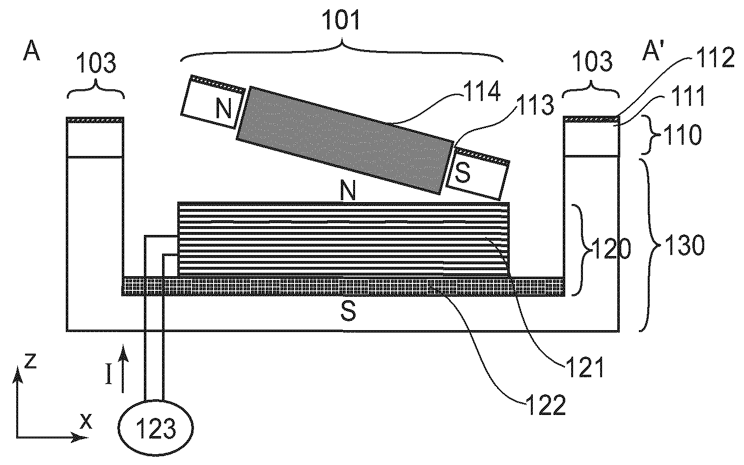
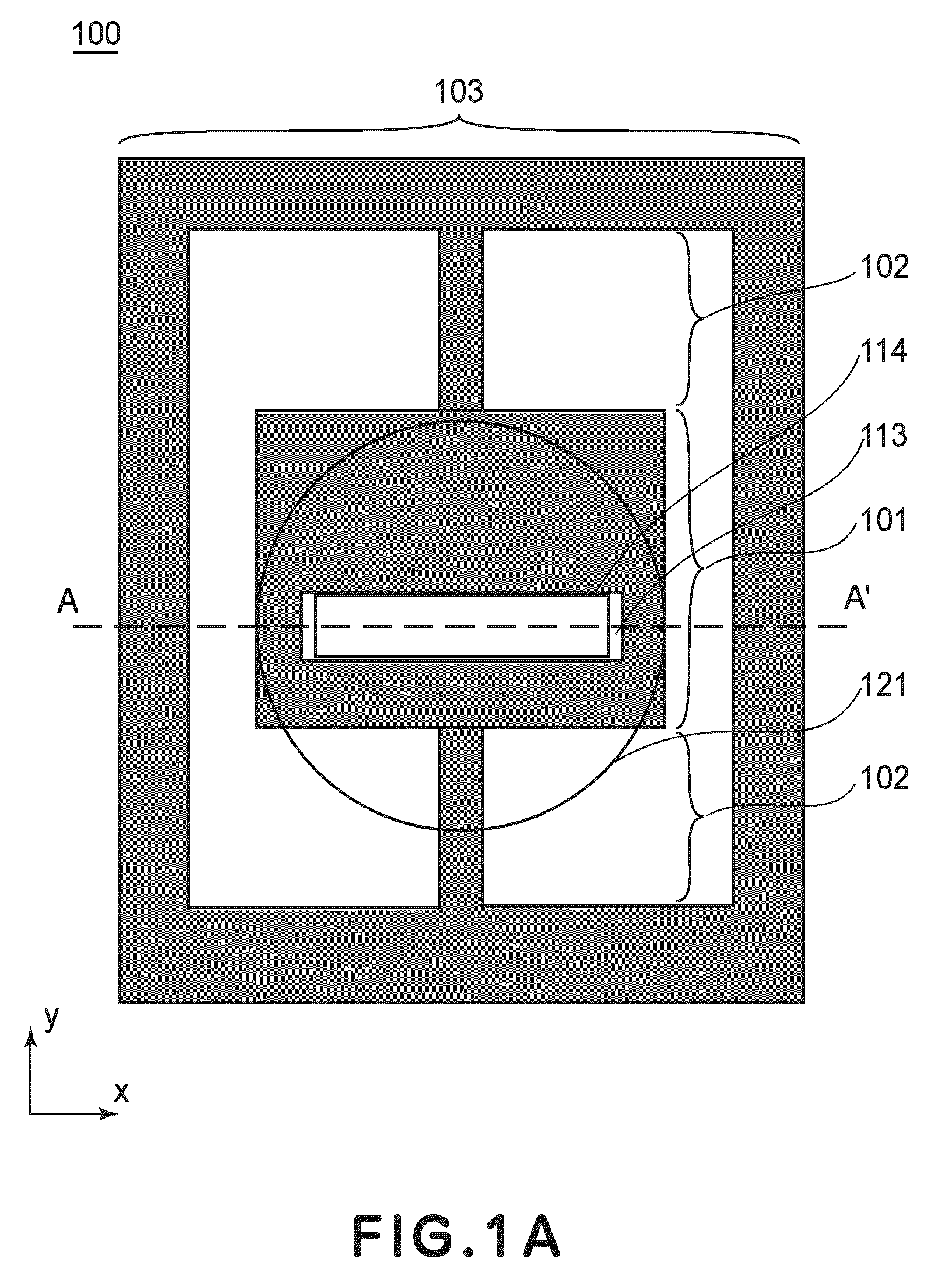
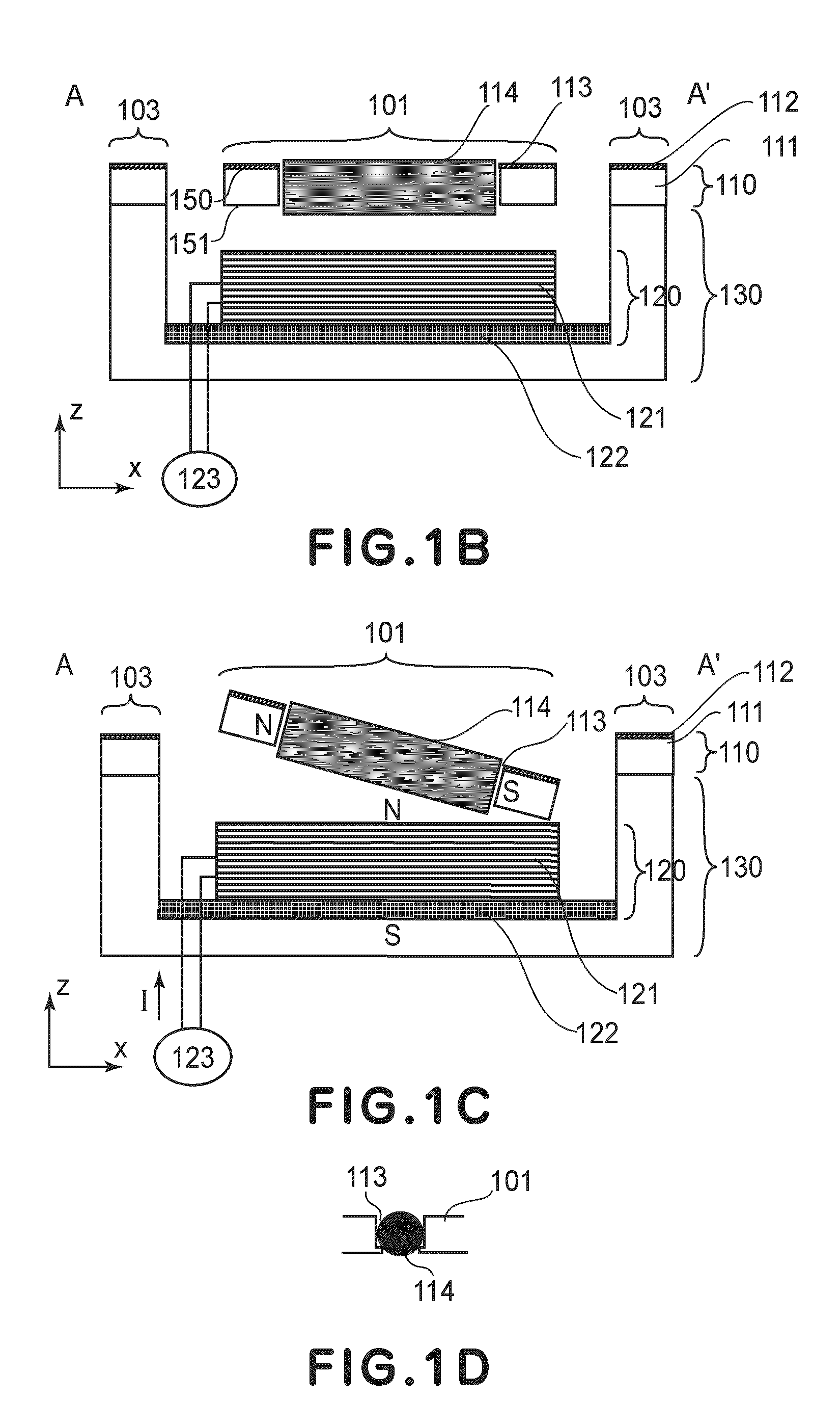
[0044]Referring to several drawings, the structure of an optical deflector 100 according to a first embodiment, using an oscillator device of the present invention, will be explained. FIG. 1A is a top plan view thereof, and FIG. 1B is a sectional view taken along a line A-A′ in FIG. 1A. As shown in these drawings, the optical deflector 100 comprises a structure in which a tip portion 110 made through MEMS technique and an electromagnetic coil member 120, constituting a driving mechanism, are installed on a jig 130. With regard to the size of the structure, for example, it is about 5 mm in length, about 5 mm in width and around 3 mm in height.
[0045]The tip portion 110 will be explained in detail with reference to FIG. 1A and FIG. 1B. In these drawings, for better understanding, the size and the relative ratio are illustrated with exaggeration or modification. The tip portion 110 is comprised of an oscillator 101 supported for oscillation, a torsion spring 102 which is a resilient sup...
second embodiment
[0069]Next, the structure of an optical deflector 400 according to a second embodiment using an oscillator device of the present invention, will be explained with reference to the drawings. FIG. 4A is a top plan view of the optical deflector. Sectional views taken along a line A-A′, a line B-B′, a line C-C′ and a line D-D′ in FIG. 4A are shown in FIG. 4B, FIG. 4C, FIG. 4D and FIG. 4E, respectively. The basic structure, driving method, operational effects are similar to the abovementioned first embodiment. Description of corresponding portions will be omitted here, although they are illustrated in the diagrams.
[0070]In this embodiment, the optical deflector 400 comprises an oscillator 101 and a passive oscillator 104. A through-hole 112 and a permanent magnet 114 are formed only in the oscillator 101. More specifically, the oscillator device comprises plural oscillators 101 and 104 and plural torsion springs 102a and 102b, and these oscillators and torsion springs are placed on a str...
third embodiment
[0082]The structure of an optical deflector 800 according to a third embodiment using an oscillator device of the present invention, will be explained with reference to the drawings. FIG. 6A is a top plan view of the optical deflector. A sectional view taken along a plane extending along a line P-P in FIG. 6A and being perpendicular to the sheet of the drawing is shown in FIG. 6B. The basic structure and driving method are similar to the abovementioned second embodiment. In FIG. 6A, denoted at 801 is a first oscillator, and denoted at 802 is a second oscillator. Denoted at 803 is a first torsion spring, and denoted at 804 is a second torsion spring. Denoted at 805 is a magnetic member, and denoted at 806 is a through-hole. Denoted at 807 is a magnetic member setting surface, and denoted at 808 is a supporting member. Denoted at 812 is an oscillation central axis. Like the preceding embodiment, the through-hole 806 extends through the oscillator, from its top surface to its bottom su...
PUM
 Abstract
Description
Claims
Application Information
 - R&D
- Intellectual Property
- Life Sciences
- Materials
- Tech Scout
- Unparalleled Data Quality
- Higher Quality Content
- 60% Fewer Hallucinations
Browse by: Latest US Patents, China's latest patents, Technical Efficacy Thesaurus, Application Domain, Technology Topic, Popular Technical Reports.
© 2025 PatSnap. All rights reserved.Legal|Privacy policy|Modern Slavery Act Transparency Statement|Sitemap|About US| Contact US: help@patsnap.com


