
Transmit/receive switch

Active Publication Date: 2009-02-05
MEDIATEK USA INC
View PDF7 Cites 294 Cited by
  • Summary
  • Abstract
  • Description
  • Claims
  • Application Information

AI Technical Summary

Benefits of technology

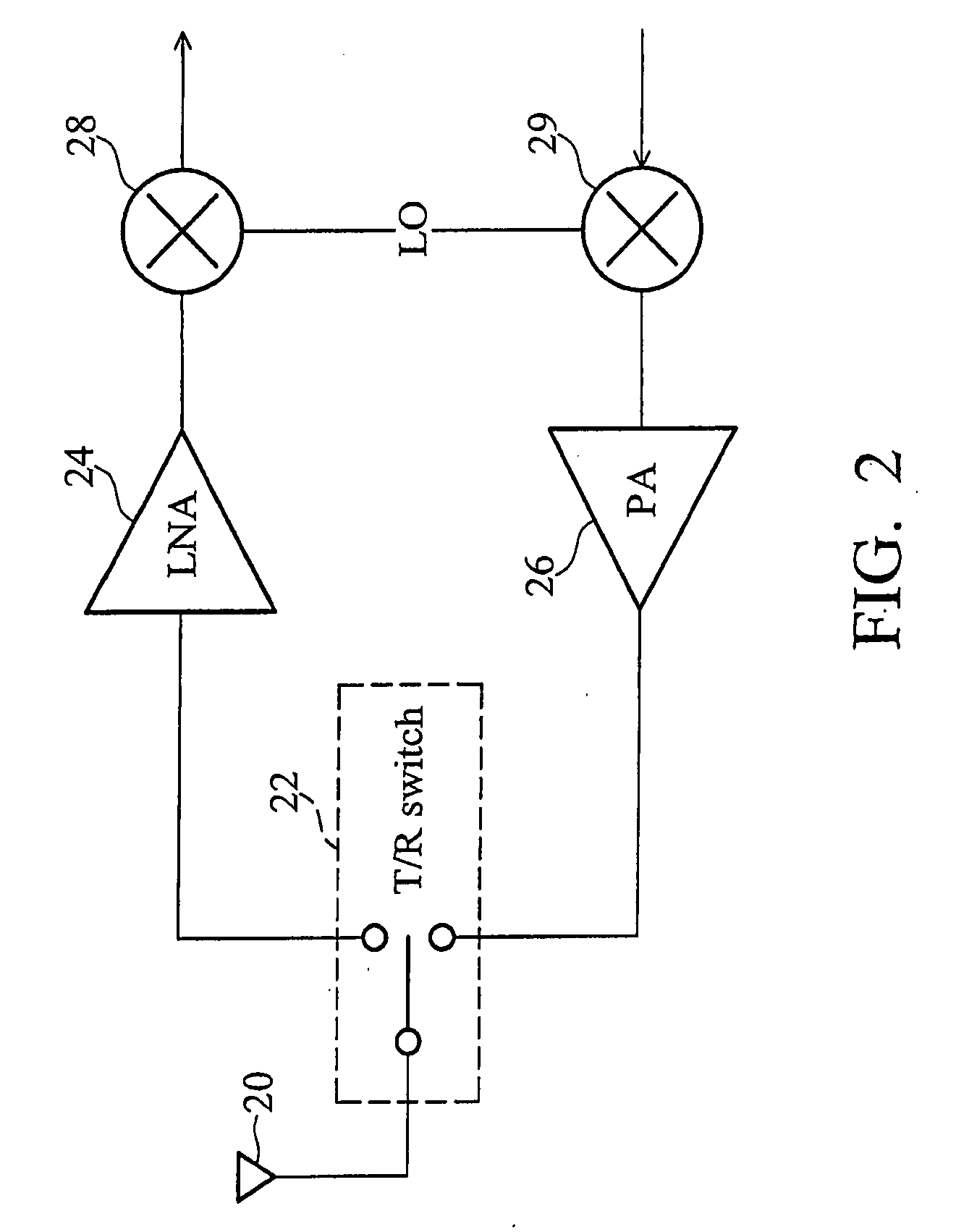
[0010]According to the invention, a radio frequency integrated circuit (RFIC) comprises a transmitter module, a receiver module, and a transmit/receive switch. The transmitter module converts an outgoing baseband signal to an outgoing RF signal, is disabled during signal reception, and comprises a power amplifier transmitting the outgoing RF signal. The receiver module converts an incoming RF signal to an incoming baseband signal, is disabled during signal transmission, and comprises a low noise amplifier receiving the incoming RF signal. The transmit/receive switch, coupled to the power amplifier and the low noise amplifier, comprises an impedance matching circuit and a voltage scaling circuit. The impedance matching circuit, coupled to the power amplifier and the low noise amplifier, provides impedance matching for the incoming and outgoing RF signals. The voltage scaling

Problems solved by technology

However, since the impedance matching circuit connects to both the transmitter and receiver, and since the transmitter and the receiver typically employ transistor devices of different thickness and power supply level, the transmit / receive switch presents reliability issues when high voltage swing is coupled to transistor devices with thin oxide, resulting in oxide breakdown and circuit failure.

Method used


Image

  • Transmit/receive switch
  • Transmit/receive switch
  • Transmit/receive switch

Examples


Embodiment Construction

[0020]The following description is of the best-contemplated mode of carrying out the invention. This description is made for the purpose of illustrating the general principles of the invention and should not be taken in a limiting sense. The scope of the invention is best determined by reference to the appended claims.

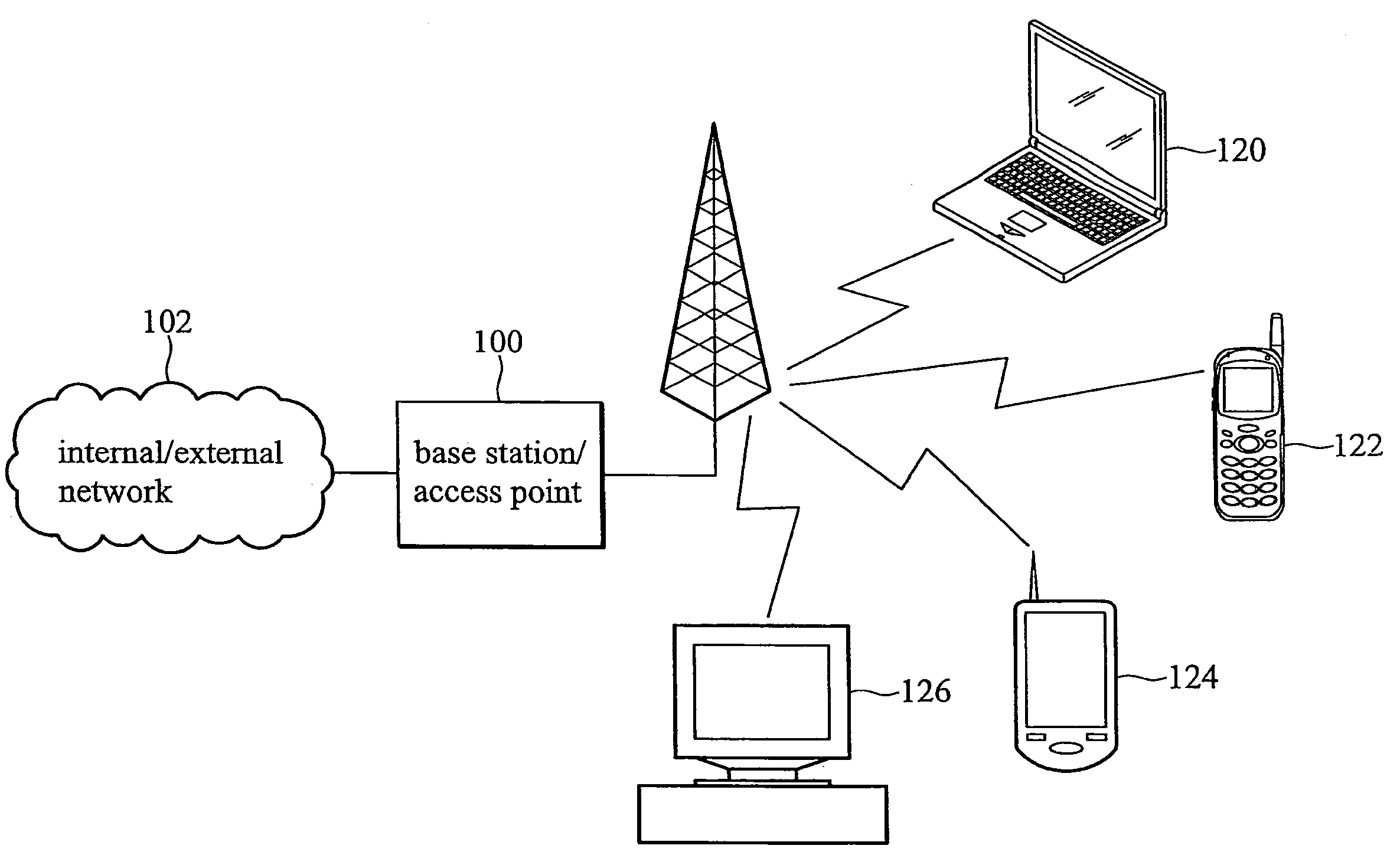
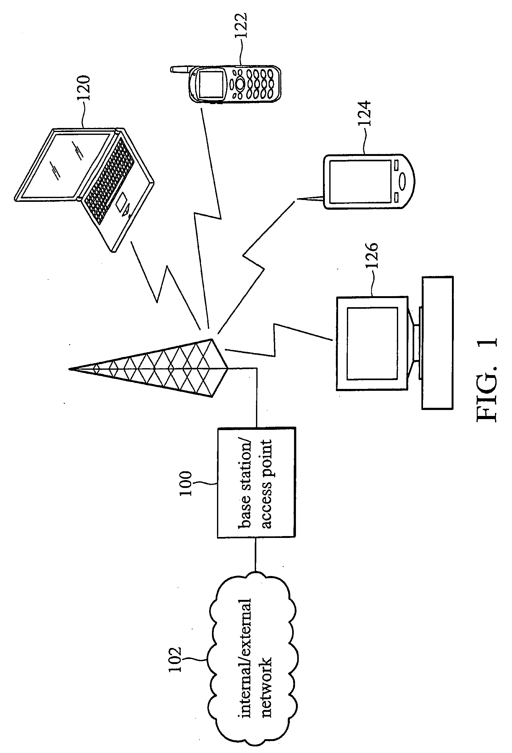
[0021]FIG. 1 is a block diagram of an exemplary wireless communication system according to the invention, comprising base station (BS) / access point (AP) 100, internal / external network 102, notebook computer 120, cellular phone 122, personal digital assistant (PDA) 124, and personal computer 126. Internal / external network 102 is coupled to Base station / access point 100, and then to notebook computer 120, cellular phone 122, personal digital assistant 124, and personal computer 126.

[0022]Base station / access point 100 accesses data via internal / external network 102, which may be an internal network such as local area network, or an external network such as the internet. B...


PUM


Abstract

A radio frequency (RF) transmit / receive switch. The transmit / receive switch comprises an impedance matching circuit and a voltage scaling circuit. The impedance matching circuit matches an incoming RF signal to a low noise amplifier and an outgoing RF signal from a power amplifier. The voltage scaling circuit, coupled to the impedance matching circuit, the power amplifier, and the low noise amplifier, attenuates the outgoing RF signal to a scaled signal within a breakdown voltage of a transistor device in the low noise amplifier during transmission of the outgoing RF signal.

Description

BACKGROUND OF THE INVENTION[0001]1. Field of the Invention[0002]The invention relates to wireless communication, and in particular to a transmit / receive switch and a radio frequency integrated circuit (RFIC) for use in wireless communication.[0003]2. Description of the Related Art[0004]In half-duplex communication systems, either the transmitter or receiver would be ON at any given time. Such systems generally adopt one single antenna and a transmit / receive switch, wherein the switch performs the selection of transmitting or receiving paths.[0005]Communication systems support wireless and wired communications between specific communication devices. Such communication systems range from national and / or international cellular telephone systems, the Internet, to point-to-point in-home wireless networks. Each type of communication system is constructed, and hence operates, in accordance with one or more communication standards. For instance, wireless communication systems may operate in...

Claims


Application Information

Patent Timeline
IPC IPC(8): H04B1/44
CPCH03F1/223H03F1/565H03F3/24H03F2203/7239H03F2200/211H03F2200/294H03F3/72
Inventor SIU, CHRISTOPHER
Owner MEDIATEK USA INC
Learn More