
Optical information reproducing system

a technology of optical information and reproducing system, which is applied in the field of optical information reproducing system, can solve the problems of difficult to ignore the higher-order resonance of an optical pickup, the loss of optical pickup tracking capability, so as to prevent the loss of gain margin, the effect of increasing the tracking capability of the optical pickup

Inactive Publication Date: 2009-02-05
TAIYO YUDEN KK
View PDF5 Cites 0 Cited by
  • Summary
  • Abstract
  • Description
  • Claims
  • Application Information

AI Technical Summary

Benefits of technology

[0010]It is an object of the present invention to provide an optical-information reproducing system in which the tracking capability of an optical pickup can be increased, and in which the number of occurrences in which the optical pickup fails to track a groove can be reduced, by increasing a gain margin.
[0013]Advantages of the optical-information reproducing system according to the aspect of the present invention are described below. In other words, the higher-order resonance frequency of the optical pickup is made lower than the wobble frequency, whereby a gain margin can be prevented from being decreased because of a peak of the wobble frequency. Because a decrease in the gain margin can be minimized, the tracking capability of the optical pickup is increased, and the number of occurrences in which the optical pickup fails to track the groove is reduced.
[0014]According to the aspect of the present invention, the optical-information reproducing system can be obtained, in which the tracking capability of the optical pickup can be increased, and in which the number of occurrences in which the optical pickup fails to track the groove can be reduced, by increasing the gain margin.

Problems solved by technology

Because of this, a higher-order resonance having a frequency of about 10 kHz to 40 kHz have become a significant problem, which is mainly caused by elastic deformation of movable units (objective-lens-holding units) of optical-pickup-drive devices.
However, when the gain in a lower range is made large, it becomes difficult to ignore the higher-order resonance of an optical pickup.
This leads to a problem that the tracking capability of the optical pickup is decreased, and that the optical pickup fails to track a groove.
Accordingly, because a change in the rotational speed between the inner and outer peripheral areas becomes large, the above-described problem easily occurs.
However, when the higher-order resonance frequency HF exceeds 40 kHz because the weight of lenses of optical pickups has been reduced, problems described below have arisen.
However, when tracking is performed, no rotational speed control is performed on the optical-information recording medium at an instant at which an optical pickup is caused to track a groove.
Accordingly, the tracking capability of the optical pickup is decreased, and the optical pickup fails to track the groove in some cases.

Method used


Image

  • Optical information reproducing system
  • Optical information reproducing system
  • Optical information reproducing system

Examples


Embodiment Construction

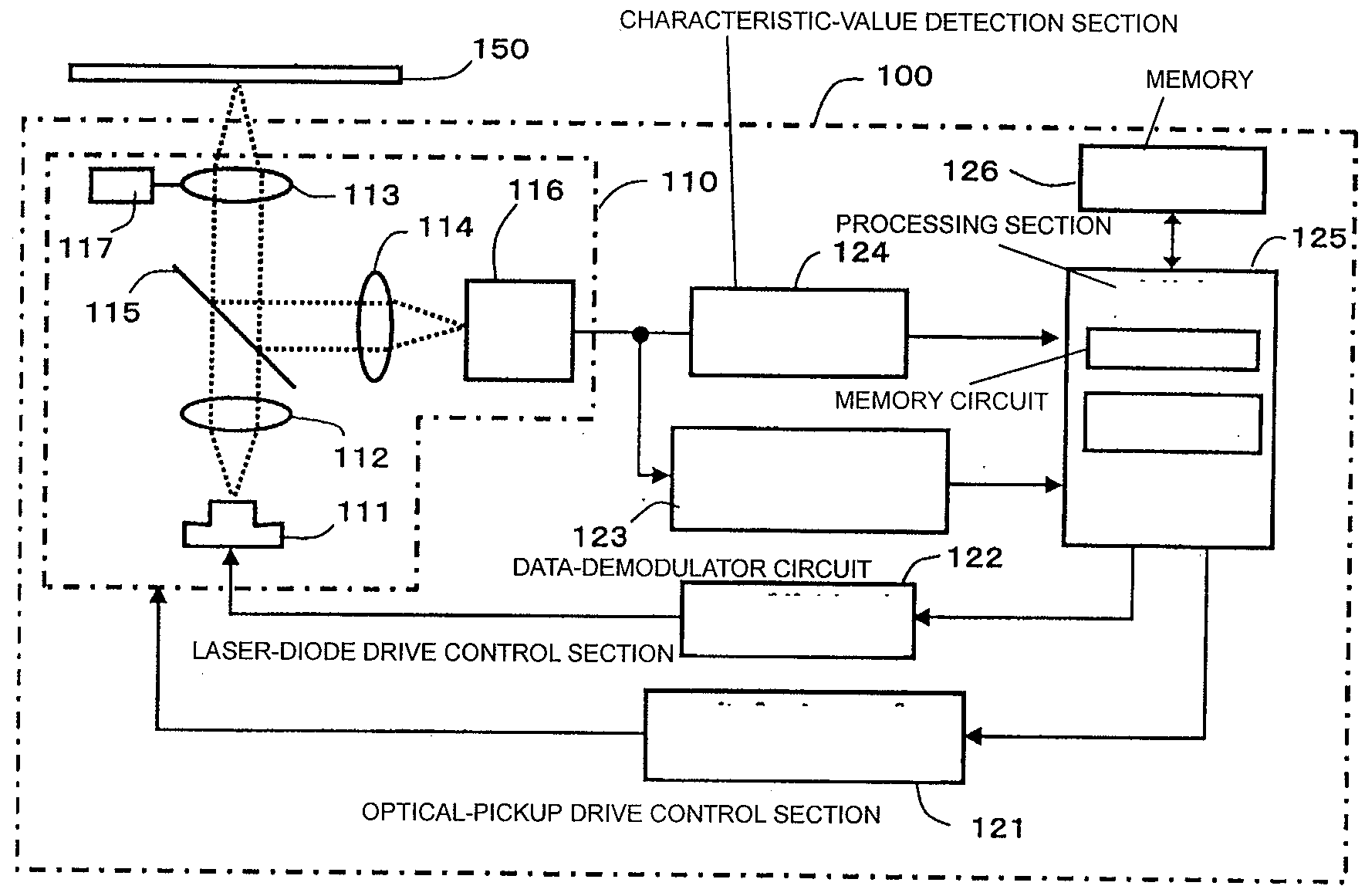
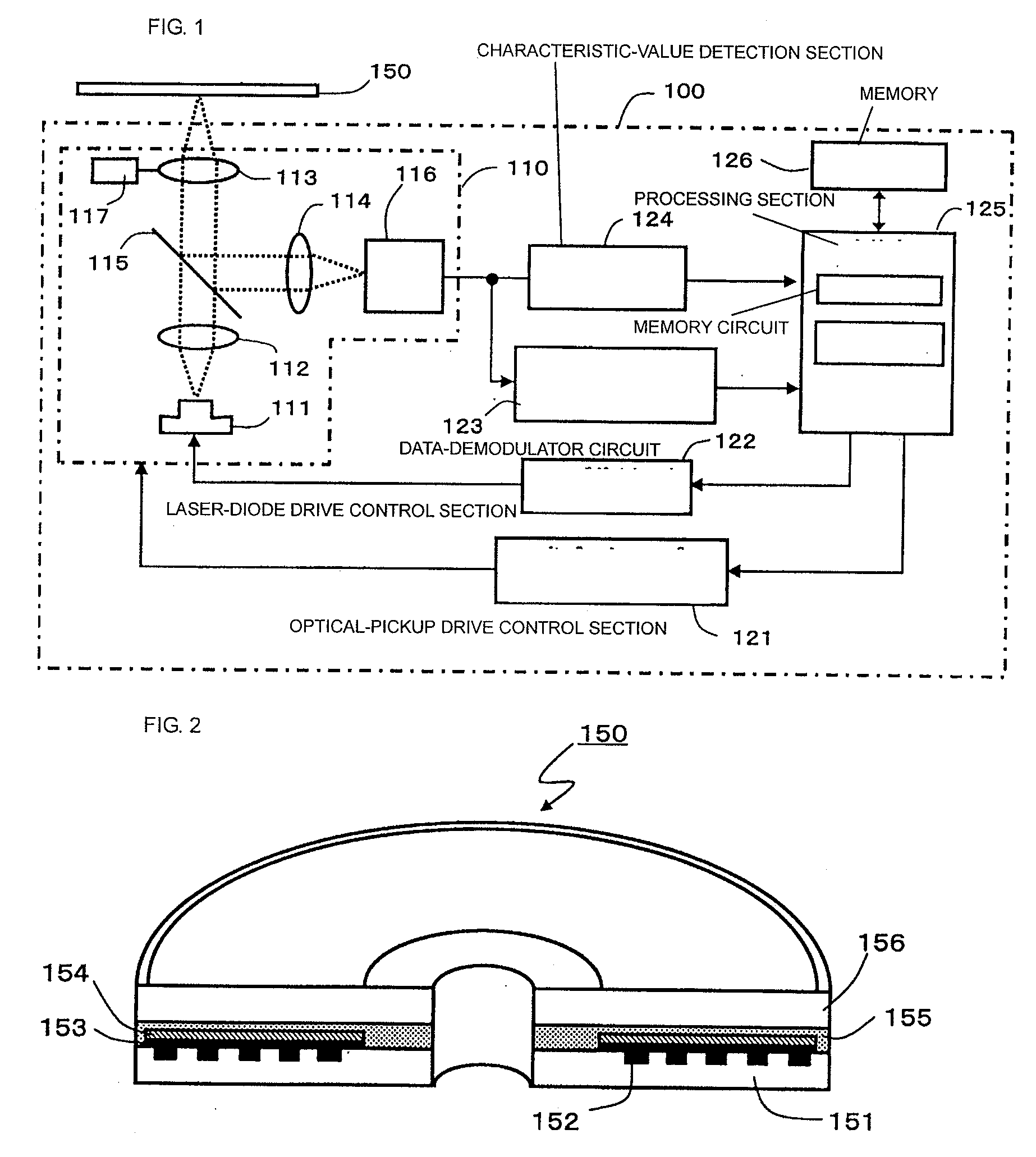
[0021]FIG. 1 is described below as a functional block diagram of a recording apparatus according to an embodiment of the present invention. An optical-disk reproduction apparatus 100 includes a memory 126, a processing section 125, a laser-diode drive control section 122, a data-demodulator circuit 123, a characteristic-value detection section 124, an optical pickup 110, an optical-pickup drive control section 121, a rotation control section (not shown) and a motor (not shown) that are used for an optical-information recording medium 150, a servo control section (not shown) used for the optical pickup 110, and so forth. In the memory 126, data that is being processed, data obtained as a processing result, data that is referred to in processing (for example, strategic data corresponding to each media identification (ID)), or the like is stored. The processing section 125 includes a central processing unit (CPU) that performs processing, and a memory circuit in which a program that al...


PUM


Abstract

An optical-information reproducing system is provided, in which the tracking capability of an optical pickup can be increased, and in which the number of occurrences in which the optical pickup fails to track a groove can be reduced, by increasing a gain margin and by ensuring the gain margin. In the optical-information reproducing system, an optical-information recording medium is rotated at a fixed linear velocity of about 3.49 m / s, and the optical pickup is caused to track the groove to irradiate the groove with laser light, whereby information recorded on the optical-information recording medium can be reproduced. A higher-order resonance frequency of the optical pickup that is generated when the optical pickup is caused to track the groove can be made lower than a wobble frequency that is reproduced using the groove without performing rotation control on the optical-information recording medium.

Description

BACKGROUND OF THE INVENTION[0001]1. Field of the Invention[0002]The present invention relates to an optical-information reproducing system, which includes an optical-information recording medium and an optical disk apparatus, for reproducing information that is recorded on the optical-information recording medium.[0003]2. Description of the Related Art[0004]A write-once compact disk (CD) (a so-called compact-disk recordable (CD-R) disk) has the following configuration: a spiral groove, to which an optical head is guided and which is used to record information, is provided in one surface of an optically transparent substrate having a diameter of 12 cm and a thickness of 1.2 mm; and a recording layer and a reflecting layer are formed in this order on a surface in which the groove is formed. The groove has a wobble which is formed in such a manner that meandering is repeated at a fixed period along a running direction in order to allow accurate position information to be obtained. The ...

Claims


Application Information

Patent Timeline
IPC IPC(8): G11B7/00
CPCG11B7/0935
Inventor SHIMIZU, ATSUO
Owner TAIYO YUDEN KK
Learn More