
Method and Procedure for Detecting Cable Length in a Storage Subsystem with Wide Ports

Inactive Publication Date: 2009-01-29
IBM CORP
View PDF21 Cites 42 Cited by
  • Summary
  • Abstract
  • Description
  • Claims
  • Application Information

AI Technical Summary

Benefits of technology

[0013]The illustrative embodiments further provide a mechanism to calibrate the high speed transmitter / receiver pair characteristics, and, thus, to optimize the transmission performance between subsystems. The mechanism mitigates the need for frequent error correction and does not incur the performance degradation associated with error correction techniques.

Problems solved by technology

With significantly disparate cable lengths, it is difficult to optimize the high speed interface for both short and long cables.
Furthermore, some scenarios may occur in which a short cable is inadvertently, or possibly deliberately, replaced with a long cable.
It is quite impractical to provide a wide SFP for optical ports.
Using a wide SFP for copper cabling would be more likely, but a significant cost adder would be required.
Some things that can affect high speed signaling include impedance variation caused by unexpected electrical discontinuities along the transmission path, high speed driver / receiver circuit defects, improper mating contacts caused by bent or damaged connector pins, incomplete connector mating caused by mechanical or installation problems, and signal coupling between adjacent signal paths.
Individual components are tested to a performance range, but tolerance buildup can cause attenuation beyond nominal design targets.
Therefore, there is an exposure to maverick defects.
However, often this is not the case, and such defects are introduced into the final system integration process.
A common technique is to wrap the high speed interfaces using a cable or wrap paths external to the subsystem; however, this does not cover the actual interface connections at the time of system integration.
As subsystem components are integrated into a system, the parametric variance from the nominal case may cause a communication failure across the high speed interface.
The price for transmission recovery may be realized in lost performance.
The mechanism under-margins transmitter output to failure for each external port and even for each PHY within a wide port.
In another exemplary embodiment, the computer readable program, when executed on the computing device, further causes the computing device to average error rate for the plurality of transmitter / receiver pairs.

Method used


Image

  • Method and Procedure for Detecting Cable Length in a Storage Subsystem with Wide Ports
  • Method and Procedure for Detecting Cable Length in a Storage Subsystem with Wide Ports
  • Method and Procedure for Detecting Cable Length in a Storage Subsystem with Wide Ports

Examples


Embodiment Construction

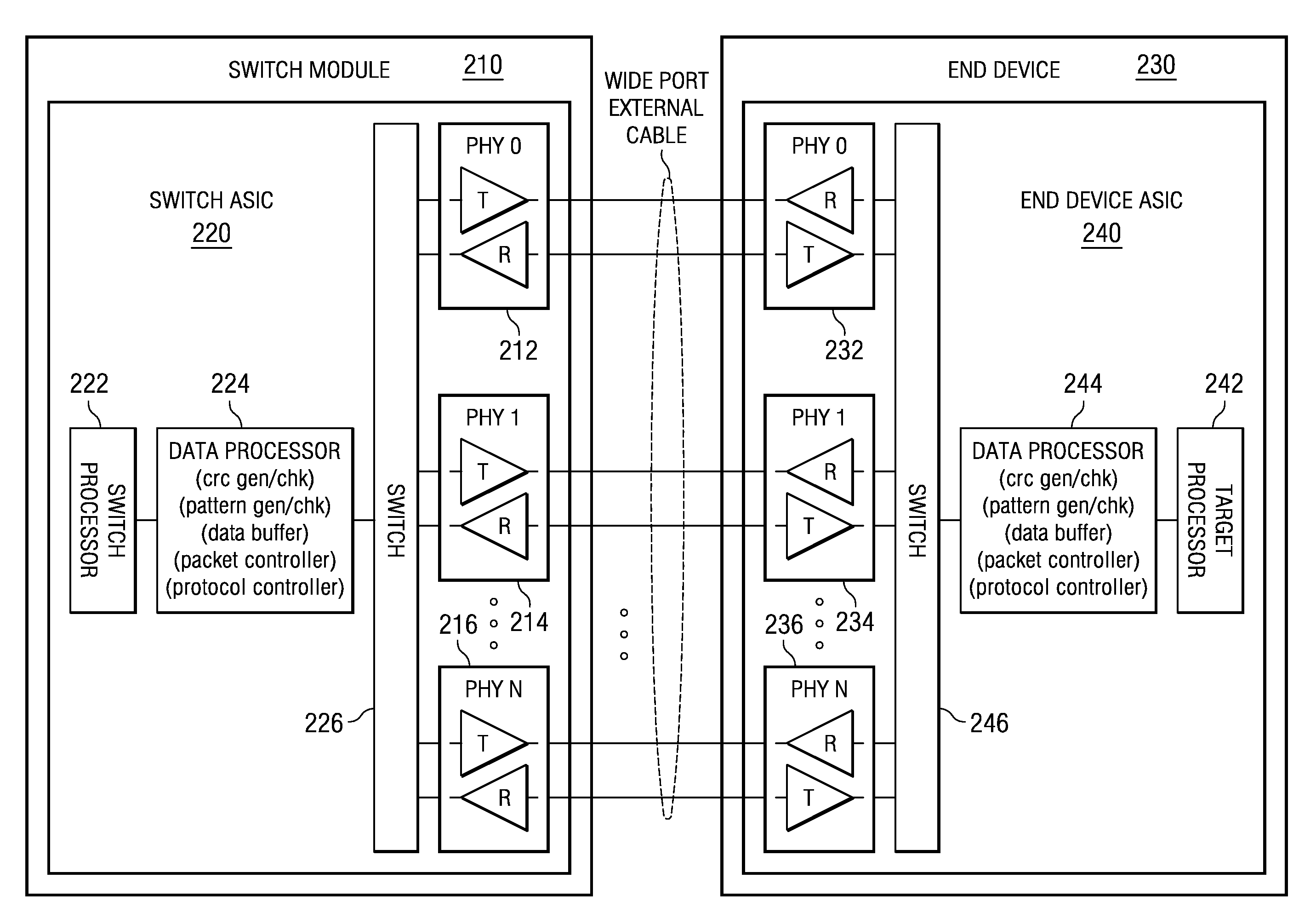
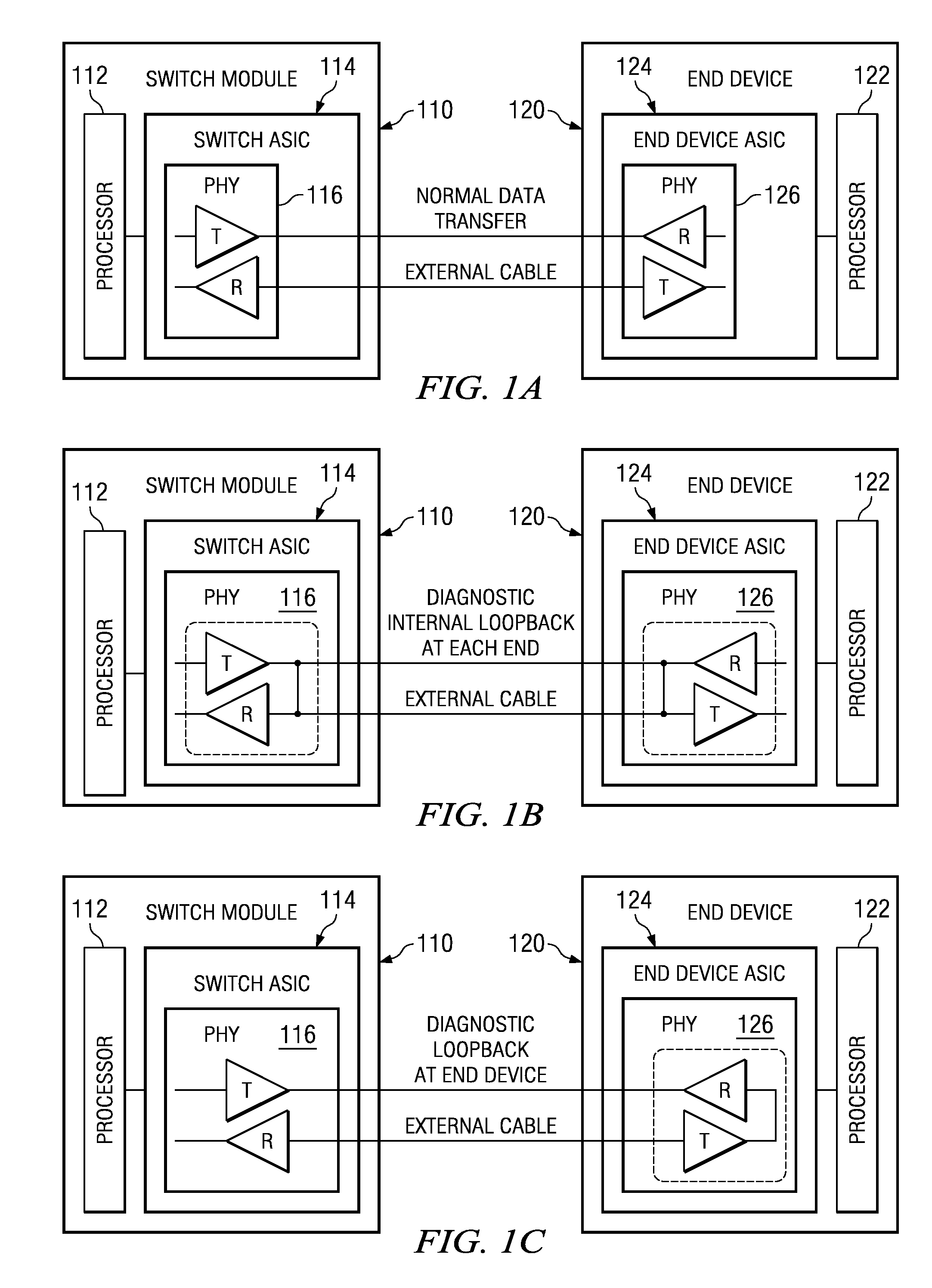
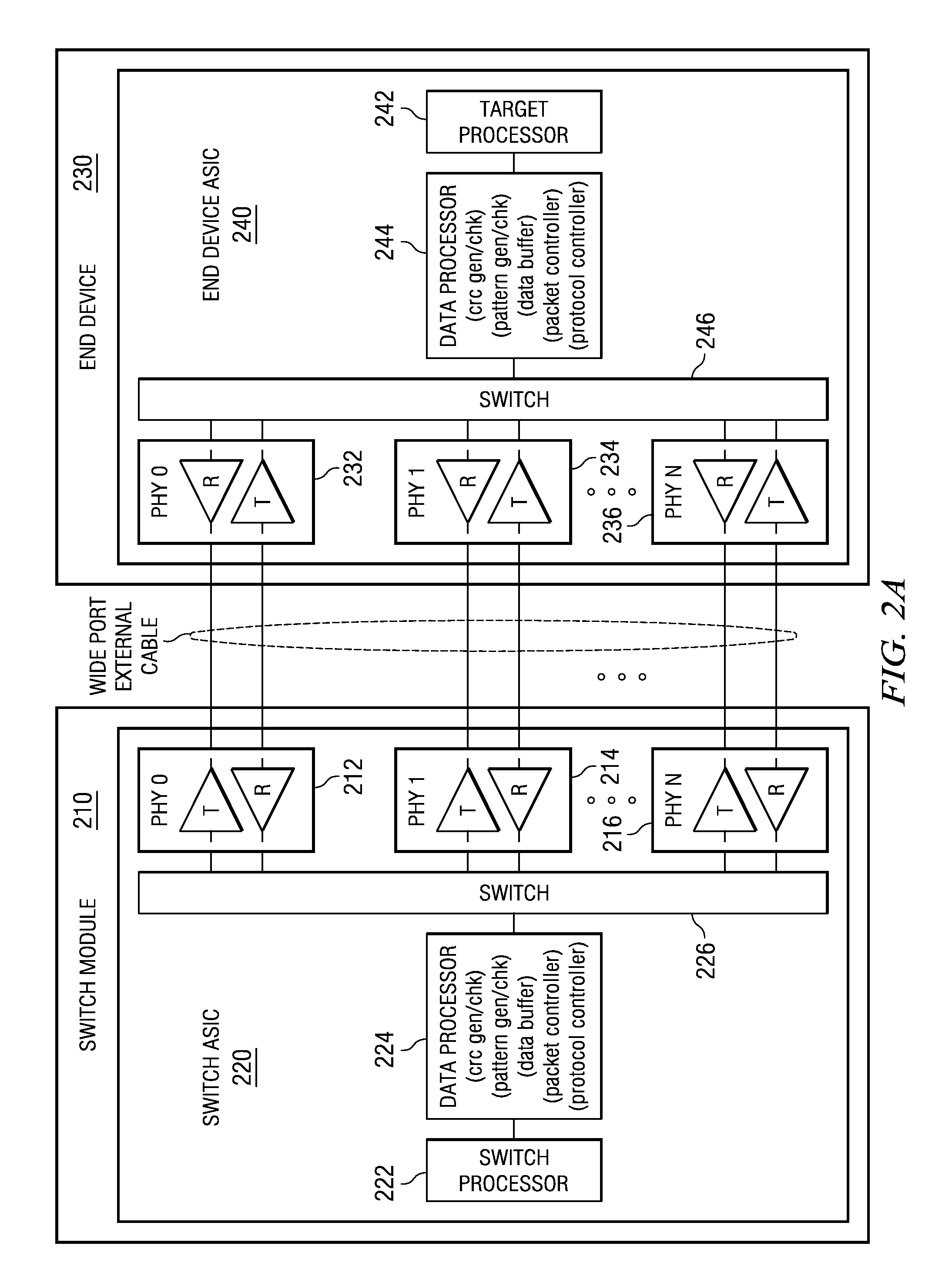
[0040]Referring to the figures, FIGS. 1A-1C are block diagrams of a narrow port in a storage network in accordance with one illustrative embodiment. More particularly with reference to FIG. 1A, switch module 110 has processor 112 and switch application specific integrated circuit (ASIC) 114. Switch ASIC 114 has physical transceiver element (PHY) 116. A PHY includes a transmitter and receiver pair. End device 120 has processor 122 and end device ASIC 124. End device ASIC 124 has PHY 126. PHY 116 is connected to PHY 126 via an external cable for normal data transfer. In one exemplary embodiment, switch module 110 may be a serial attached SCSI (SAS) switch module and end device 120 may be a SAS end device.

[0041]With reference now to FIG. 1B, PHY 116 in switch ASIC 114 and PHY 126 in end device ASIC 124 are configured for diagnostic internal loopback at each end. In accordance with the illustrative embodiment, PHY 116 and PHY 126 have the capability to connect the transmitter to the rec...


PUM


Abstract

A mechanism detects cable length in a storage subsystem with wide ports. The mechanism uses in-situ bidirectional cable wrapping for determining different cable lengths. The mechanism under-margins transmitter output to failure for each external port and even for each PHY within a wide port. Based on the transition point from “good” wrap to “bad” wrap, the cable length may be determined. The transition point identifies if the cable is long or short, at which point the optimum tuning parameters can accordingly be set. A calibration mechanism calibrates the high speed transmitter / receiver pair characteristics, and, thus, optimizes the transmission performance between subsystems. The calibration mechanism mitigates the need for frequent error correction and does not incur the performance degradation associated with error correction techniques.

Description

BACKGROUND[0001]1. Technical Field[0002]The present application relates generally to an improved data processing system and method. More specifically, the present application is directed to a method and procedure for detecting cable length in a storage subsystem with wide ports.[0003]2. Description of Related Art[0004]In storage network systems, high speed serial differential interfaces are used to interconnect multiple storage components. For example, in BladeCenter® products from IBM Corporation, a serially attached SCSI (SAS) switch may be used to interconnect the server blades to external storage, such as a typical storage enclosure. The server blades may be directly connected to the SAS switch via an internal high speed fabric. The SAS switch is connected to the external storage via external SAS cables.[0005]Generally, multiple cable lengths are required for attaching storage at different distances from the SAS switch. The initial release of the first BladeCenter® storage produ...

Claims


Application Information

Patent Timeline
IPC IPC(8): H04B3/46
CPCG06F13/4068
Inventor CAGNO, BRIAN JAMESLUCAS, GREGG STEVENTRUMAN, THOMAS STANLEY
Owner IBM CORP
Learn More