
Chromomodal dispersion apparatus and methods

Inactive Publication Date: 2009-01-22
RGT UNIV OF CALIFORNIA
View PDF10 Cites 4 Cited by
  • Summary
  • Abstract
  • Description
  • Claims
  • Application Information

AI Technical Summary

Benefits of technology

[0015]A tunable dispersion device is disclosed that attains high dispersion, low dispersion slope, and low loss performance by chromatically dispersing a light wave and creating modal dispersion of the dispersed light with a multimode waveguide. The results and implementation of this device are demonstrated through the use of the Zemax® optical design program (Zemax® is a registered trademark of the Zemax® Development Corporation). The present invention makes use of the chromatic dispersion of a diffraction grating and the modal dispersion of a waveguide to maximize and control the dispersion value, while minimizing higher-order dispersive effects, i.e. a chromomodal dispersion device. The device was tested in three versions: one completely free space version, and two versions in which a waveguide (glass and silicon) is used.
[0019]In some embodiments, the dispersion slope equalizer removes at least some of the higher-order dispersion effects in the multimode waves. Where the higher-order dispersion effects comprise a non-uniform spread of multimode waves of different wavelengths, the dispersion slope equalizer controls the angular spread of the wavelengths. Preferably, the dispersion slope equalizer affects a substantially constant angular spread between the wavelengths to flatten the dispersion curve.
[0029]Where some of the higher-order dispersion effects comprise a non-uniform spread of multimode waves of different wavelengths, the angular spread of the wavelengths is controlled.

Problems solved by technology

A tunable dispersion device is disclosed that attains high dispersion, low dispersion slope, and low loss performance by chromatically dispersing a light wave and creating modal dispersion of the dispersed light with a multimode waveguide.

Method used


Image

  • Chromomodal dispersion apparatus and methods
  • Chromomodal dispersion apparatus and methods
  • Chromomodal dispersion apparatus and methods

Examples


Embodiment Construction

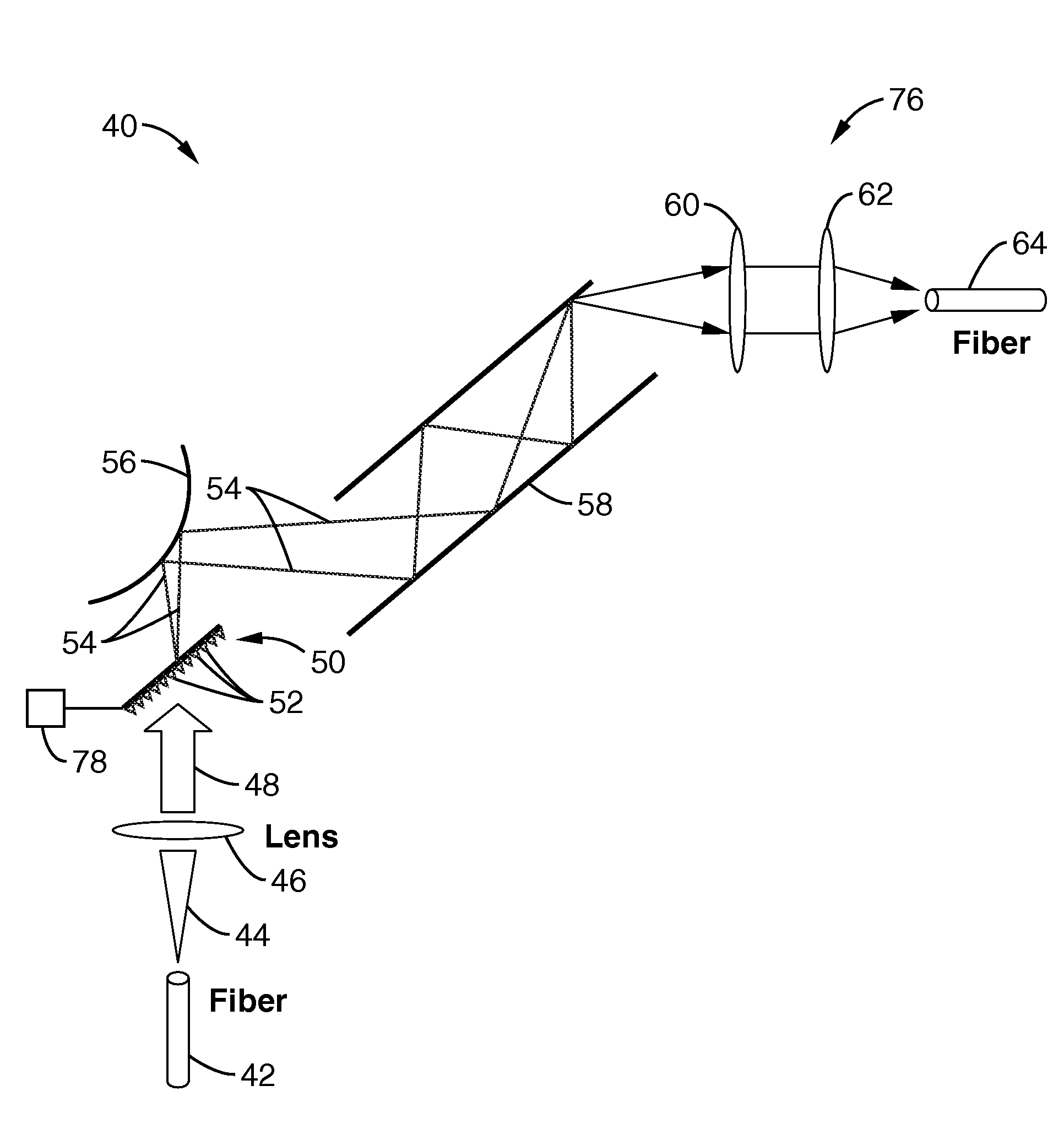
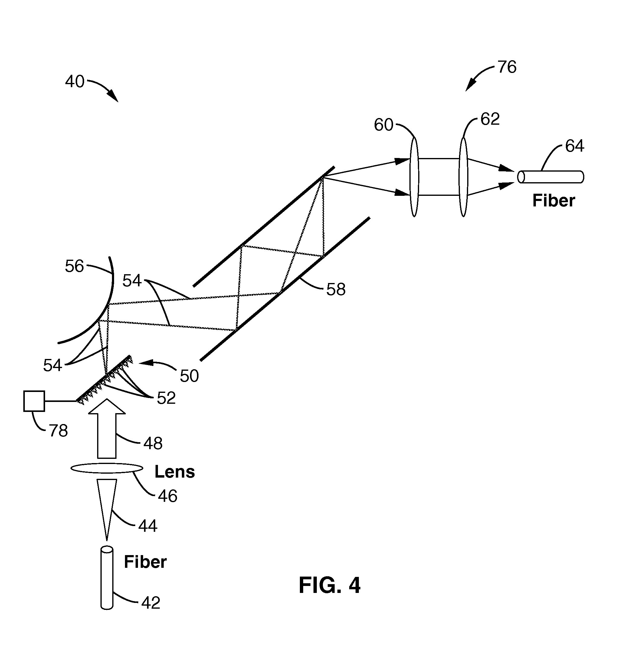
[0048]Referring more specifically to the drawings, for illustrative purposes the present invention is embodied in the apparatus generally shown in FIG. 4 through FIG. 14. It will be appreciated that the apparatus may vary as to configuration and as to details of the parts, and that the method may vary as to the specific steps and sequence, without departing from the basic concepts as disclosed herein.

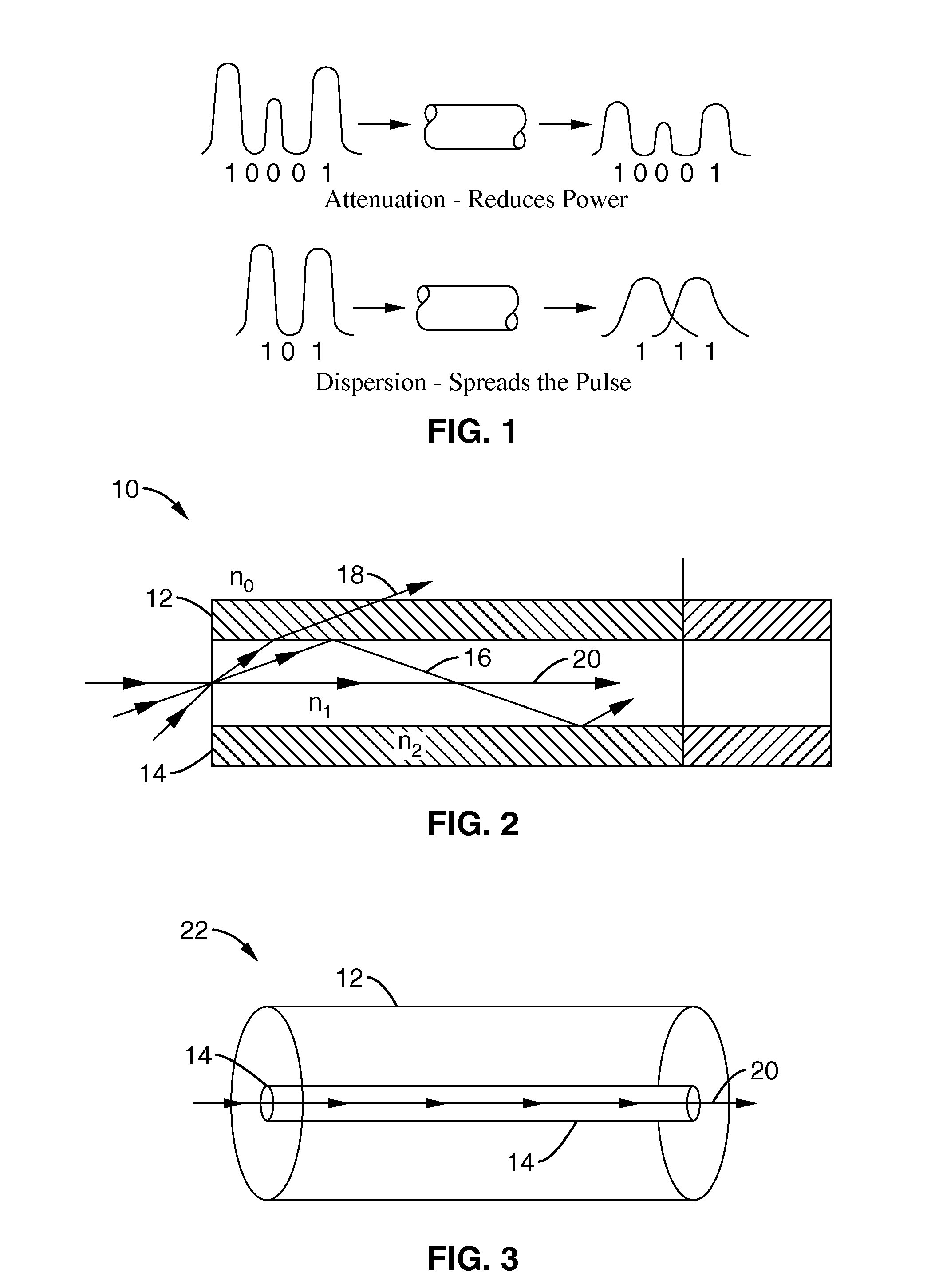
[0049]1. Wave Dispersion in Optical Fibers

[0050]Dispersion, although often undesirable, is an effect that is inherent in nature and understanding of the mathematical and natural origins of this phenomenon is important in efforts to counteract it.

[0051]It is clear that the refractive index in a dispersive medium is frequency dependent, thus waves propagating with different frequencies will travel at different speeds. This has a very important effect upon data transmission. If it is assumes that information is contained in pulses, and if these pulses travel as truly monochromatic waves, d...


PUM


Abstract

A system and method to chromomodally generate dispersion in light waves. The system and method may be used to control dispersive effects of an optical element such as a single-mode fiber. A light beam from the optical element is first collimated and then directed on to a spatially diffractive element where it is spatially dispersed into various chromatic frequency components. This frequency-separated light is then imparted onto a dispersion slope equalizer, and then passed into a highly multimode waveguide, where it is further dispersed. The light is then collected and focused back into an outgoing fiber-optic or other optical device.

Description

CROSS-REFERENCE TO RELATED APPLICATIONS[0001]This application claims priority from, and is a 35 U.S.C. § 111(a) continuation of, co-pending PCT international application serial number PCT / US2005 / 032126, filed on Sep. 7, 2005, incorporated herein by reference in its entirety, which claims priority from U.S. provisional application Ser. No. 60 / 607,793, filed on Sep. 7, 2004, incorporated herein by reference in its entirety.INCORPORATION-BY-REFERENCE OF MATERIAL SUBMITTED ON A COMPACT DISC[0002]Not ApplicableSTATEMENT REGARDING FEDERALLY SPONSORED RESEARCH OR DEVELOPMENT[0003]This invention was made with Government support under Grant No. N66001-00-1-8035 and Grant No. N66001-98-1-8925 awarded by DARPA. The Government has certain rights in this invention.NOTICE OF MATERIAL SUBJECT TO COPYRIGHT PROTECTION[0004]A portion of the material in this patent document is subject to copyright protection under the copyright laws of the United States and of other countries. The owner of the copyrig...

Claims


Application Information

Patent Timeline
IPC IPC(8): G02B5/18
CPCG02B6/29311H04B10/25133G02B6/29392G02B6/29314
Inventor JALALI, BAHRAMSIENICKI, TODD
Owner RGT UNIV OF CALIFORNIA
Learn More