Image projection system

Inactive Publication Date: 2009-01-15
DAI NIPPON PRINTING CO LTD
View PDF18 Cites 33 Cited by
  • Summary
  • Abstract
  • Description
  • Claims
  • Application Information

AI Technical Summary

Benefits of technology

[0019]the invisible light ray-shielding means is placed in front of or inside the image p

Problems solved by technology

However, an approach to interlocking the hand-held pointer and the digitizer requires the pointer to contact the screen, so the scope of applications of the projection system is limited, and the accuracy of acquired positional information is low.

Method used


Image

  • Image projection system
  • Image projection system
  • Image projection system

Examples


production example 1

[0201]The following components were uniformly kneaded and dispersed, whereby an ink A for the formation of reflection patterns was prepared.

Polyurethane-based resin (trade name “Urearnou40.0 parts by weight 2466” manufactured by Arakawa ChemicalIndustries, Ltd.):Nitrocellulose:2.0 parts by weightCuring agent (trade name “TAKENATE D-110N”4.0 parts by weightmanufactured by MITSUI CHEMICALSPOLYURETHANES, INC.):Isopropyl alcohol:5.0 parts by weightMethyl ethyl ketone:6.0 parts by weightEthyl acetate:4.0 parts by weightTitanium oxide:39.0 parts by weight (surface-treated with silica, average particlediameter: 0.3 μm)

[0202]Next, the upper portion of the base material A 121 having a thickness of 125 μm and composed of polyethylene terephthalate (PET) was coated with a solution prepared by dissolving, in methyl ethyl ketone (MEK), 100 parts by weight of pentaerythritol triacrylate, 0.03 part by weight of an acrylic acid copolymer-based leveling agent (trade name “BYK361” manufactured by BYK...

production example 2

[0204]A solution was prepared by dissolving, in methyl isobutyl ketone (MIBK), 100 parts by weight of a monomer having a polymerizable acryloyl group at any one of its terminals and having a nematic-isotropic transition temperature around 110° C. (having a molecular structure represented by the chemical formula (9)), 3.0 parts by weight of a chiral agent having a polymerizable acryloyl group at any one of its terminals (having a molecular structure represented by the chemical formula (12)), and 4 parts by weight of a photopolymerization initiator diphenyl-(2,4,6-trimethylbenzoyl)phosphine oxide (trade name: Lucirin TPO, manufactured by BASF), and the solution was defined as an ink B for the formation of reflection patterns.

[0205]Next, the primer layer 122 having a thickness of 1 μm was formed on the same base material A 121 as that of Production Example 1 in the same manner as in Production Example 1. Thus, the substrate A 120 was obtained.

[0206]The above ink B for the formation of ...

production example 3

[0207]An infrared ray-reflecting ink was prepared by dissolving, in methyl isobutyl ketone, 100 parts by weight of a monomer having a polymerizable acryloyl group at any one of its terminals and having a nematic-isotropic transition temperature around 110° C. (having a molecular structure represented by the compound (11)), 3.0 parts by weight of a chiral agent having a polymerizable acryloyl group at any one of its terminals (having a molecular structure represented by the above chemical formula (12)), 4 parts by weight of a photopolymerization initiator (Lucirin TPO manufactured by BASF), and 0.3 part by weight of a leveling agent (BYK361 manufactured by BYK-Chemie GmbH).

[0208]The liquid crystal solution was directly applied onto the transparent base material B 240 having a thickness of 125 μm and composed of PET by a gravure printing method, and was cured by being irradiated with an ultraviolet ray, whereby the infrared ray-diffusing-and-reflecting substrate B 220 was produced.

[02...


PUM


Abstract

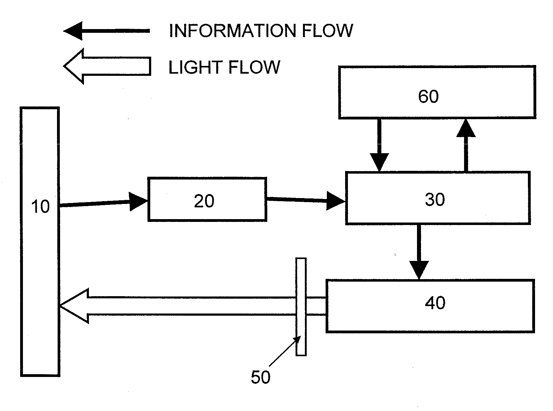
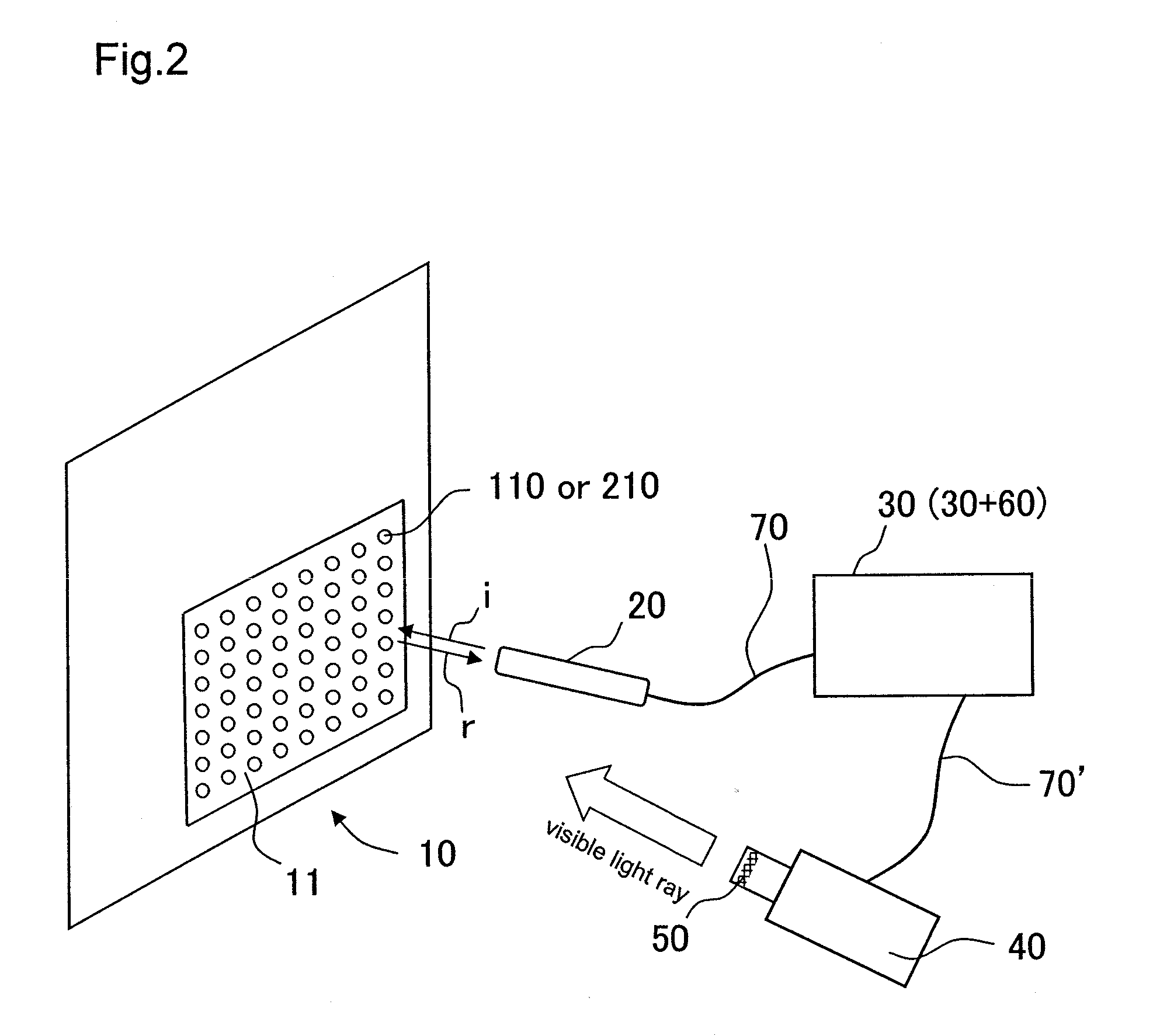
Provided is an image projection system including a screen, an input terminal, an image processing unit, an image projector, and invisible light ray-shielding member, characterized in that: the screen has a pattern-printed sheet having reflection patterns for transmitting positional information by reflecting invisible light rays or absorption patterns for transmitting positional information by absorbing invisible light rays; the input terminal has an invisible light ray-applying portion, detects a reflected light ray of an invisible light ray, which is applied from the invisible light ray-applying portion and reflected from a specific site of the pattern-printed sheet, reads positional information of any one of the reflection patterns or any one of the absorption patterns, and outputs the positional information to the image processing unit; the image processing unit converts the positional information input from the input terminal into image information A, and transfers the image information A to the image projector; the image projector converts the image information A transferred from the image processing unit into visible light rays, and projects the visible light rays on the screen; and the invisible light ray-shielding means is placed in front of or inside the image projector, and removes the invisible light ray from the visible light rays to be projected. The present invention can provide the image projection system in which, even when a screen is large, the positional information of the screen can be simply input in a non-contact fashion with high accuracy, and image information converted from the input positional information can be further converted into visible light rays to be projected.

Description

TECHNICAL FIELD[0001]The present invention relates to an image projection system for continuously projecting static images and / or moving images on a screen.BACKGROUND ART[0002]A projection system including a projection screen and a projector has been conventionally known, and various proposals concerning the system have been made (see, for example, Patent Documents 1 to 6).[0003]In addition, Patent Document 7 proposes an optical projection system including means for generating a signal indicating the position of a hand-held pointer on a display screen, for example, a digitizer for specifying the x and y coordinates of the hand-held pointer.[0004]However, an approach to interlocking the hand-held pointer and the digitizer requires the pointer to contact the screen, so the scope of applications of the projection system is limited, and the accuracy of acquired positional information is low.[0005][Patent Document 1] Japanese Patent Application Laid-open No. 2005-43712[0006][Patent Docum...

Claims


Application Information

Patent Timeline
IPC IPC(8): G09G5/00
CPCG06F3/0308G06F3/03542G06F3/0346
Inventor TAZAKI, KEIKONAKAMURA, RUNAMAENISHI, SATOKO
Owner DAI NIPPON PRINTING CO LTD
Why Eureka
Try Eureka