Scattering medium internal observation apparatus, image pickup system, image pickup method and endoscope apparatus

a technology of internal observation apparatus and scattering medium, which is applied in the field of optical observation techniques, can solve the problems of increasing patient burden and prolonging surgery, and achieve the effect of reducing the distance from the surfa

Active Publication Date: 2009-01-08
OLYMPUS CORP
View PDF7 Cites 41 Cited by
  • Summary
  • Abstract
  • Description
  • Claims
  • Application Information

AI Technical Summary

Benefits of technology

[0030]An endoscope apparatus according to the present invention includes: an endoscope having an insertion portion provided with a distal end portion capable of bringing at least a distal end face which an observation window faces into close contact with a surface of a living body tissue to be an observation object; a suction apparatus having a sheath for suction to be mounted on the endoscope and which interiorly includes the distal end portion and in which a distal end opening is formed on an outer peripheral side of the distal end portion, and suction section provided on a proximal end-side of the sheath for suction so as to communicate with the distal end opening and which performs suction; and distance reducing section for sucking in the living body tissue around the distal end face and in a portion opposing the distal end opening through a suction operation of the suction apparatus to reduce a distance from a surface of the living body tissue to blood vessels running inside the surface as an internal observation object tissue within an observation field of view of the observation window.

Problems solved by technology

Accordingly, since it is required that an operation be performed while cautiously identifying the positions of blood vessels, surgeries tend to be prolonged.
A prolonged surgery leads to an increased burden on the patient.

Method used


Image

  • Scattering medium internal observation apparatus, image pickup system, image pickup method and endoscope apparatus
  • Scattering medium internal observation apparatus, image pickup system, image pickup method and endoscope apparatus
  • Scattering medium internal observation apparatus, image pickup system, image pickup method and endoscope apparatus

Examples


first embodiment

[0087]Disclosed in embodiments of the present invention are various techniques related to the contents described below.

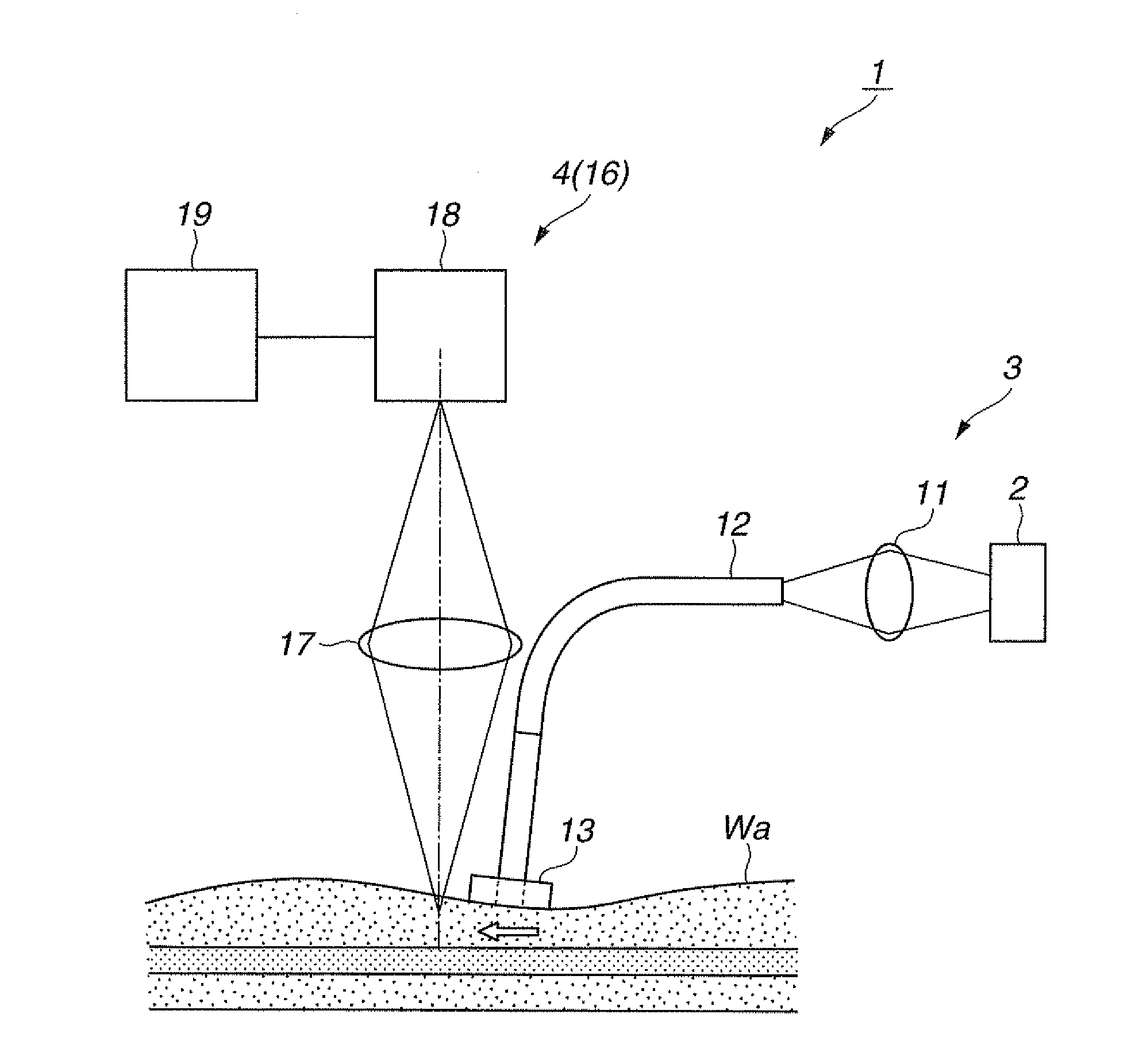
[0088]The present invention provides a scattering medium internal observation apparatus including: a light source; an illuminating apparatus that guides light from the light source to an observation object that is a scattering body; and an observation optical system for observing the observation object illuminated by the illuminating apparatus, wherein the illuminating apparatus has a light-guiding member that guides light from the light source to a surface of the observation object, and a light-shielding member that covers the surface of the observation object and which shields light reflected or scattered in the vicinity of the light-guiding member of the observation object is disposed in the vicinity of an end portion of the light-guiding member on an observation object-side.

[0089]In addition, the present invention provides a scattering medium internal observatio...

second embodiment

[0157]A second embodiment of the present invention will now be described with reference to FIGS. 7 and 8. As shown in FIG. 7, a scattering medium internal observation apparatus 31 shown in the second embodiment is the scattering medium internal observation apparatus 1 shown in the first embodiment provided with a plurality of illuminating apparatuses 3.

[0158]The second embodiment is configured such that distal end portions of light-guiding members 12 of two illuminating apparatuses 3 are connected using a stay or the like so that respective rows of optical fibers 12a are approximately parallel to each other and that regions of virtual light sources respectively formed by the illuminating apparatuses 3 overlap each other.

[0159]According to the scattering medium internal observation apparatus 31, providing the plurality of illuminating apparatuses 3 enables a region in which the inside of fat is illuminated to be widened. As a result, images of blood vessels inside the fat can be crea...

third embodiment

[0163]A third embodiment of the present invention will now be described with reference to FIGS. 10 and 11.

[0164]As shown in FIG. 10, a scattering medium internal observation apparatus 51 shown in the third embodiment is the scattering medium internal observation apparatus 1 shown in the first embodiment or the scattering medium internal observation apparatus 31 shown in the second embodiment in which the configuration of the illuminating apparatus 3 has been changed.

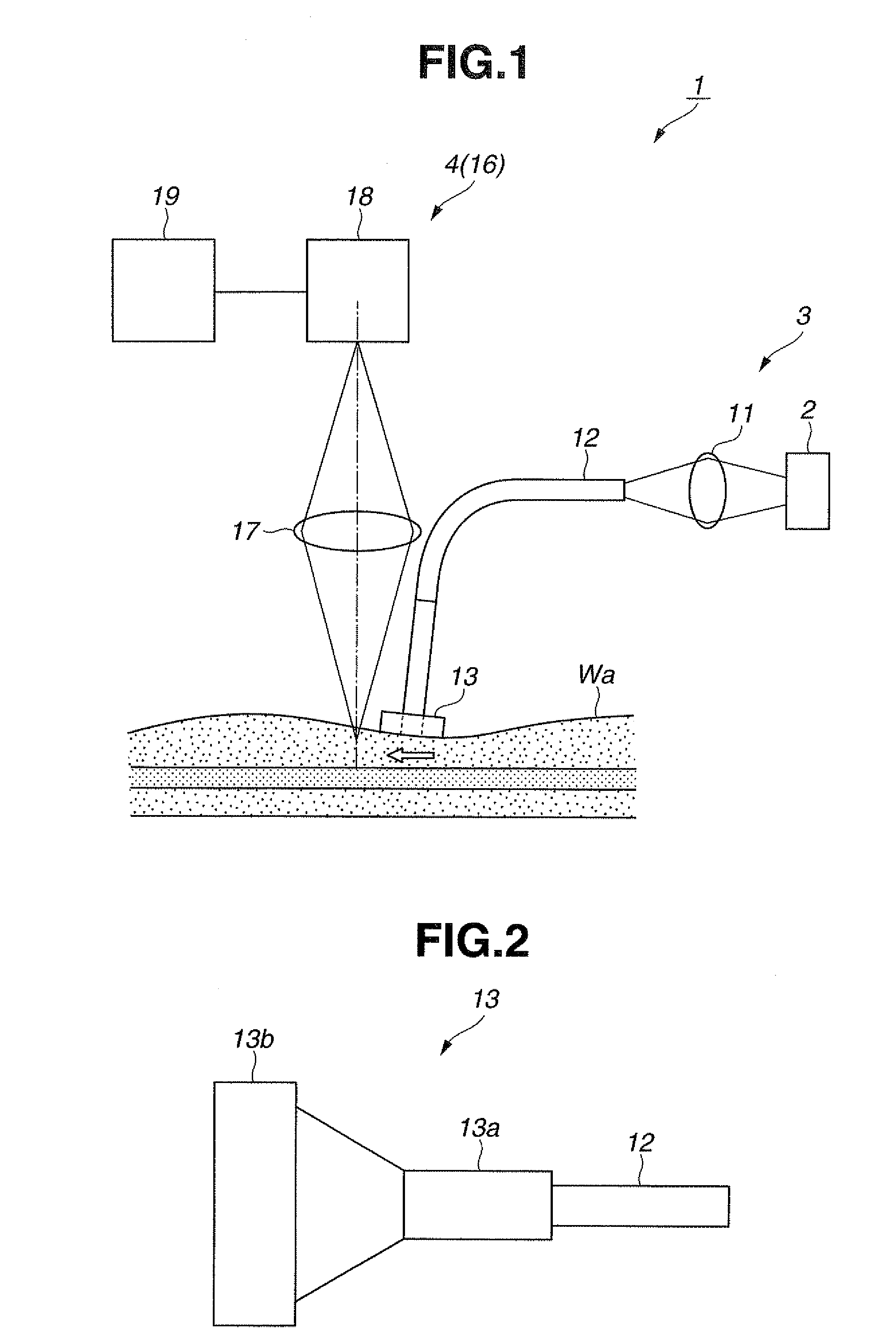
[0165]As shown in FIG. 11, with the scattering medium internal observation apparatus 51, an observation object-side end portion of a light-guiding member 12 that configures the illuminating apparatus 3 is housed inside a hollow needle-like member 52 of which at least a distal end is inserted into an observation object Wa.

[0166]In the third embodiment, a widening portion 13b of a light-shielding member 13 is provided with a plurality of through-holes 13d arranged in a row along a width direction in place of the slits 13c....


PUM


Abstract

A scattering medium internal observation apparatus according to the present invention includes: a light source; an illuminating apparatus that guides light from the light source to an observation object that is a scattering body; and an observation optical system for observing the observation object illuminated by the illuminating apparatus, wherein the illuminating apparatus has a light-guiding member that guides light from the light source to a surface of the observation object, and a light-shielding member that covers the surface of the observation object and which shields light reflected or scattered in the vicinity of the light-guiding member of the observation object is disposed in the vicinity of an end portion of the light-guiding member on an observation object-side.

Description

CROSS REFERENCE TO RELATED APPLICATION[0001]This application is a continuation application of PCT / JP2007 / 053926 filed on Mar. 1, 2007 and claims benefit of Japanese Applications No. 2006-068289 filed in Japan on Mar. 13, 2006, No. 2006-071198 filed in Japan on Mar. 15, 2006, No. 2006-073181 filed in Japan on Mar. 16, 2006, No. 2006-088781 filed in Japan on Mar. 28, 2006, and No. 2006-088782 filed in Japan on Mar. 28, 2006, the entire contents of each of which are incorporated herein by their reference.BACKGROUND OF THE INVENTION[0002]1. Field of the Invention[0003]The present invention relates to a technique for optically observing an observation object site within a living body, and in particular, to a scattering medium internal observation apparatus, an image pickup system, an image pickup method and an endoscope apparatus for observing blood vessels, nerves and the like existing within a living body.[0004]2. Description of the Related Art[0005]When performing a surgical operation...

Claims


Application Information

Patent Timeline
Patent Type & Authority Applications(United States)
IPC IPC(8): H04N7/18
CPCA61B1/00165A61B1/07A61B5/0059A61B1/00096A61B5/0075A61B5/441A61B5/489A61B5/0064
Inventor ISHIWATA, HIROSHINISHIDA, HIROYUKIHANDA, KEIJIHARANO, KENJIASADA, DAISUKE
Owner OLYMPUS CORP
Why Eureka
Try Eureka