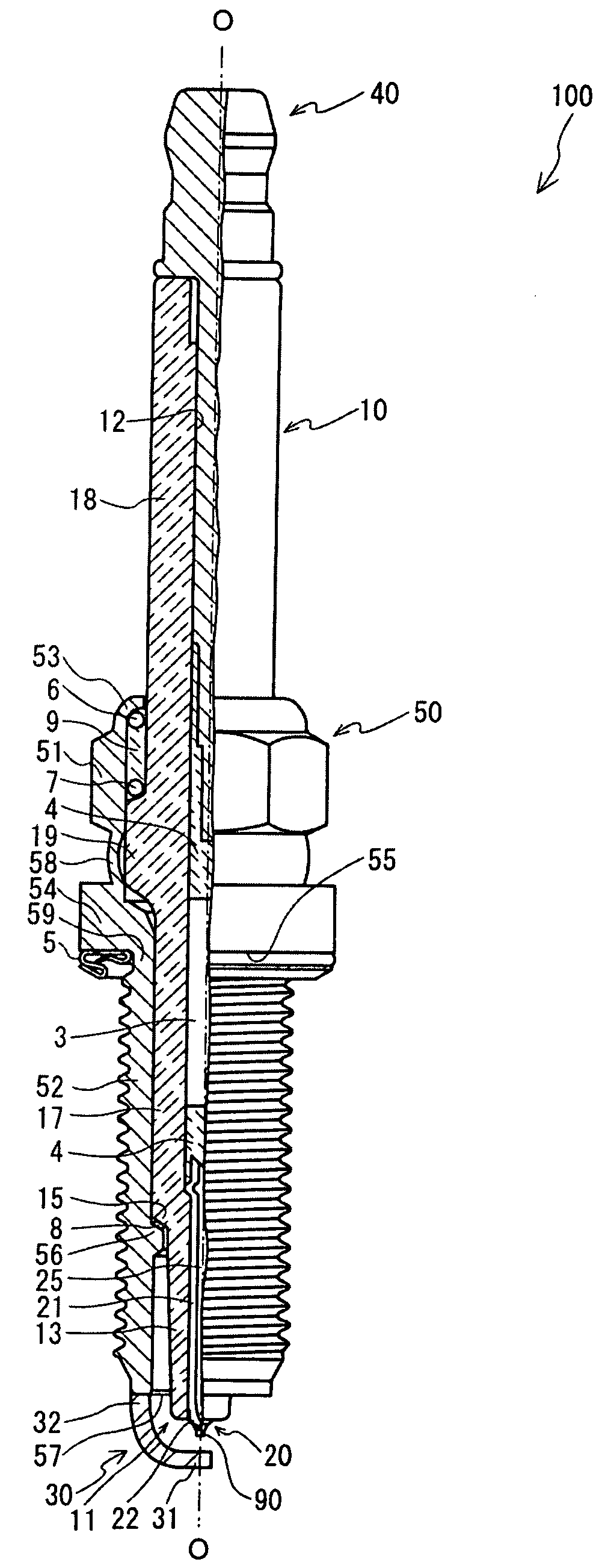
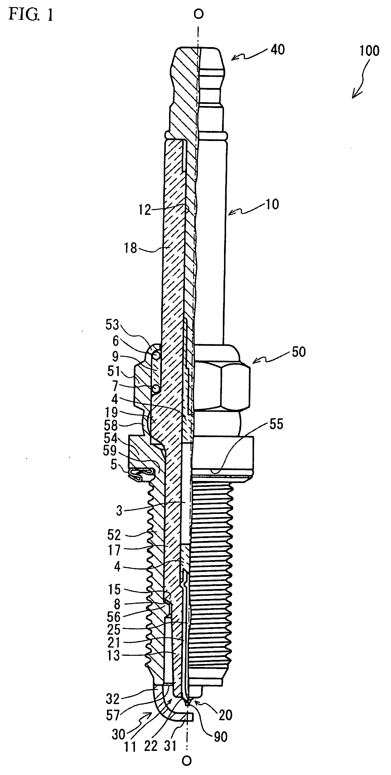
Spark plug

a technology for spark plugs and internal combustion engines, which is applied to spark plugs, machines/engines, mechanical equipment, etc., can solve problems such as internal corrosion to progress, and achieve the effects of reducing specific resistance, increasing heat dissipation performance of electrode materials, and effectively increasing spark wear resistan

Active Publication Date: 2009-01-08
NGK SPARK PLUG CO LTD +1
View PDF6 Cites 12 Cited by
  • Summary
  • Abstract
  • Description
  • Claims
  • Application Information

AI Technical Summary

Benefits of technology

[0032]In addition, to enhance the heat dissipation performance of the electrode material which is fabricated from the electrode material and effectively increase the spark wear resistance, it is preferable to adjust the composition of the electrode material such that its specific resistance at normal temperature (20 to 25° C.) becomes not more than 15 μΩcm, as in the 13th aspect of the invention. The lower the specific resistance, the more the heating value accompanying the spark discharge of the electrode fabricated from this electrode material can be suppressed. To lower the specific resistance, it is necessary to reduce the content of the second additional element, and if that content becomes small, the thermal conductivity of the electrode material improves, so that it is possible to enhance the heat dissipation performance when the electrode material is used for the electrode, thereby making it possible to enhance the spark wear resistance.
[0033]In addition, if a ratio (σ0.2 / σB) of 0.2% proof stress (σ0.2) to tensile strength (σB) is not less than 0.4 and not more than 0.6, as in the 14th aspect of the invention, the intermetallic compounds are distributed finely and uniformly, and it is possible to increase the high-temperature oxidation resistance. If σ0.2 / σB is less than 0.4, the distribution of the intermetallic compounds becomes insufficient, possibly resulting in a decline in the high-temperature oxidation resistance. On the other hand, if σ0.2 / σB exceeds 0.6, its effect is saturated and the deformation resistance during working becomes large, so that there is a possibility that desirable workability cannot be obtained as the electrode material.

Problems solved by technology

In the case where oxides are precipitated in the parent phase of Ni of the electrode material, the precipitated oxides remain in the electrode material, and the oxides disadvantageously decompose in an environment which is set to higher temperatures than in conventional cases, possibly causing internal corrosion to progress due to oxygen.

Method used


Image

  • Spark plug
  • Spark plug
  • Spark plug

Examples


example 1

[0062]In Example 1, confirmation was made as to whether or not the high-temperature oxidation resistance of the electrode material is affected by precipitates in the parent phase of Ni. In fabricating Samples 111 to 113 of the electrode materials, a raw material was used in which 0.45 wt. % of Y as the first additional element and 0.15 wt. % of Si as the second additional element were added to 99.40% wt. % of Ni, and this raw material was melted and cast by using a vacuum melting furnace to form an ingot. Subsequently, Samples 111 to 113 of the electrode materials were fabricated by using wires obtained through hot working and wire drawing and having a cross-sectional size of 1.3×2.7 mm. Further, in fabricating Samples 114 and 115, a raw material was used in which 0.50 wt. % of Nd as the first additional element and 0.15 wt. % of Si as the second additional element were added to 99.35% wt. % of Ni, and this raw material was melted and cast by using a vacuum melting furnace to form a...

example 2

[0065]Further, an evaluation test similar to that of Example 1 was conducted by using other elements as the first additional element. In fabricating each of Samples 211 to 214 of the electrode materials, a raw material was used in which 0.50 wt. % of the first additional element and 0.15 wt. % of Si as the second additional element were added to 99.35% wt. % of Ni, and this raw material was melted and cast by using the vacuum melting furnace to form an ingot in the same way as in Example 1. Subsequently, Samples 211 to 214 of the electrode materials were fabricated by using wires obtained through hot working and wire drawing and having a cross-sectional size of 1.3×2.7 mm. It should be noted that, in Samples 211 to 213, Ho, Gd, and Sm were respectively used as the first additional element, and intermetallic compounds (Ni—Ho, Ni—Gd, and Ni—Sm) respectively precipitated in the formed electrode materials. In addition, in Sample 214, two kinds, Y and Nd, were added as the first addition...

example 3

[0067]Next, an evaluation test was conducted to confirm the effect exerted by the content of the first additional element on the grain growth of crystal grains of the electrode materials. As for Samples 311 to 319 of the electrode materials, Y was added as the first additional element, and its content was varied, while the content of Si, which is added as the second additional element, was set to 0.15 wt. %, and the content of Ni was adjusted so that the balance is Ni. Specifically, in Samples 311 to 319, the content of Y as the first additional element was set in sequence to 4.00, 3.00, 2.00, 1.00, 0.45, 0.30, 0.10, 0.05, and 0.00 (wt. %), while the content of Ni was set in sequence to 95.85, 96.85, 97.85, 98.85, 99.40, 99.55, 99.75, 99.80, and 99.85 (wt. %). Through this adjustment, the content ratio (the content of the first additional element / the content of the second additional element) between the first additional element and the second additional element in Samples 311 to 319...


PUM


Abstract

A spark plug (100) includes: a center electrode (2); and a ground electrode (30) which is to be exposed in a combustion chamber of an internal combustion engine and which forms a spark discharge gap with the center electrode (2), wherein at least one of the center electrode (20) and the ground electrode (30) contains an electrode material whose principal component is Ni and in which an intermetallic compound is precipitated at least intergranularly and intragranularly.

Description

CROSS-REFERENCE TO RELATED APPLICATIONS[0001]This application claims the benefit of Japanese Patent Application JP 2007-179066, filed Jul. 6, 2007, the entire content of which is hereby incorporated by reference, the same as if set forth at length.FIELD OF THE INVENTION[0002]The present invention relates to a spark plug for an internal combustion engine using an Ni-based alloy as the material of electrodes for effecting spark discharge.BACKGROUND OF THE INVENTION[0003]Conventionally, a spark plug for ignition is used in an internal combustion engine such as an automobile engine. A spark plug in general has a structure in which an insulator with a center electrode insertedly provided therein is held by a metal shell in such a manner as to surround the periphery of the insulator, and a spark discharge gap is formed between the center electrode and a ground electrode joined to a leading end of the metal shell. The ignition of an air-fuel mixture flowing in between the both electrodes i...

Claims


Application Information

Patent Timeline
Patent Type & Authority Applications(United States)
IPC IPC(8): H01T13/22
CPCH01T13/39H01T13/20
Inventor YOSHIMOTO, OSAMUNUNOME, KENJINAKAI, YOSHIHIRONISHIKAWA, TAICHIROTANJI, TORUYAMAZAKI, KAZUO
Owner NGK SPARK PLUG CO LTD
Why Eureka
Try Eureka