
Method of and system for variable pitch computed tomography scanning for baggage screening

a computed tomography and variable pitch technology, applied in material analysis using wave/particle radiation, instruments, nuclear engineering, etc., can solve the problems of significant cone beam artifacts in the helical weighting method and the method does not provide a continuous reconstruction of continuous data acquisition in the baggage screening application, so as to achieve less labor intensive ct baggage screening and improve image quality

Inactive Publication Date: 2009-01-01
ANLOGIC CORP (US)
View PDF53 Cites 21 Cited by
  • Summary
  • Abstract
  • Description
  • Claims
  • Application Information

AI Technical Summary

Benefits of technology

[0056]The present disclosure provides a method of and a system for variable pitch CT scanning for baggage screening. In accordance with one aspect of the disclosure, the method and system provide for scanning a continuous flow of baggage with the conveyor belt being stopped from time to time. In accordance with the one aspect of the disclosure, the method and system reconstruct projection data acquired at variable pitch due to the change of the belt speed for baggage screening. In accordance with another aspect of the disclosure, the disclosed method and system provide a more convenient, better image quality, and less labor intensive CT baggage screening scheme at checkpoint.
[0058]In one embodiment of the present disclosure, an improved image reconstruction method is provided to handle the acceleration and deceleration of the main conveyor belt. The image reconstruction method uses nutating or tilted slices for reconstruction to reduce cone-beam artifacts. The tilt angle for each slice is dynamically calculated based on the belt speed or pitch, which is defined as the ratio of the belt displacement in one gantry rotation to the detector array width along the belt movement direction.

Problems solved by technology

The helical weighting method suffers significant cone beam artifacts for the CT scanners with more than eight rows of detectors.
Furthermore, the method does not provide a continuous reconstruction of continuous data acquisition in the baggage screening application.

Method used


Image

  • Method of and system for variable pitch computed tomography scanning for baggage screening
  • Method of and system for variable pitch computed tomography scanning for baggage screening
  • Method of and system for variable pitch computed tomography scanning for baggage screening

Examples


Embodiment Construction

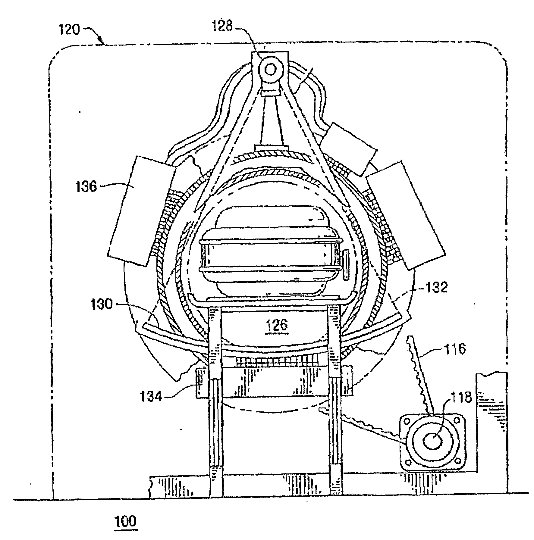
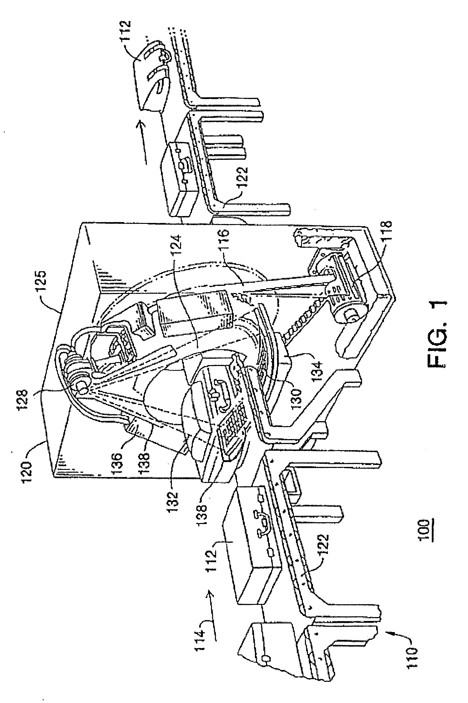
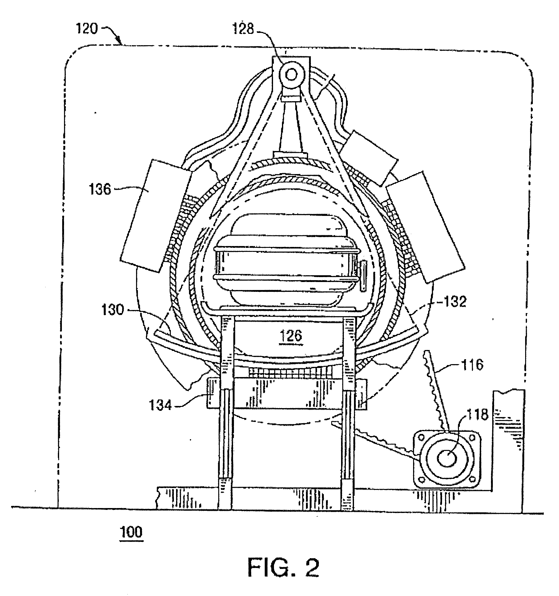
[0080]Referring to the drawings, FIGS. 1, 2 and 3 show perspective, end cross-sectional, and radial cross-sectional views, respectively, of a typical baggage scanning system 100, which includes a conveyor system 110 for continuously conveying baggage or luggage 112 in a direction indicated by arrow 114 through a central aperture of a CT scanning system 120. The conveyor system includes motor driven belts for supporting the baggage. Conveyer system 110 is illustrated as including a plurality of individual conveyor sections 122; however, other forms of conveyor systems may be used.

[0081]The CT scanning system 120 includes an annular shaped rotating platform, or disk, 124 disposed within a gantry support 125 for rotation about a rotation axis 127 (shown in FIG. 3) that is preferably parallel to the direction of travel 114 of the baggage 112. Disk 124 is driven about rotation axis 127 by any suitable drive mechanism, such as a belt 116 and motor drive system 118, or other suitable drive...


PUM

PropertyMeasurementUnit
speedaaaaaaaaaa
speedaaaaaaaaaa
widthaaaaaaaaaa

Abstract

A method of and a system for variable pitch CT scanning for baggage screening and variable pitch image reconstruction are disclosed. The method comprises decelerating conveyor belt speed when additional time is needed to render a decision on a complex bag; accelerating conveyor belt speed to its normal speed when decisions are reached on undecided bags; generating cone-beam projection data at variable scanning pitch corresponding to variable conveyor belt speed; computing a tilt angle and a distance offset for each tilted slice using the pitch values at which the cone-beam projection data is acquired for that tilted slice; generating fan-beam projection data for each tilted slice using the tilted angle and the distance offset; generating correction projection data to compensate for the error between the source trajectory and the tilted reconstruction plane; generating the corrected fan-beam projection data by adding the correction projection data to the fan-beam projection data; reconstructing tilted slices using the corrected fan-beam projection data; and interpolating the reconstructed tilted slices into axial slices.

Description

RELATED APPLICATIONS[0001]This patent application and / or patents are related to the following co-pending U.S. applications and / or issued U.S. patents, of the assignee as the present application, the contents of which are incorporated herein in their entirety by reference:[0002]“Nutating Slice CT Image Reconstruction Apparatus and Method,” invented by Gregory L. Larson, et al., U.S. application Ser. No. 08 / 831,558, filed on Apr. 9, 1997, now U.S. Pat. No. 5,802,134, issued on Sep. 1, 1998;[0003]“Computed Tomography Scanner Drive System and Bearing,” invented by Andrew P. Tybinkowski, et al., U.S. application Ser. No. 08 / 948,930, filed on Oct. 10, 1997, now U.S. Pat. No. 5,982,844, issued on Nov. 9, 1999;[0004]“Air Calibration Scan for Computed Tomography Scanner with Obstructing Objects,” invented by David A. Schafer, et al., U.S. application Ser. No. 08 / 948,937, filed on Oct. 10, 1997, now U.S. Pat. No. 5,949,842, issued on Sep. 7, 1999;[0005]“Computed Tomography Scanning Apparatus ...

Claims


Application Information

Patent Timeline
Patent Type & Authority Applications(United States)
IPC IPC(8): G01N23/00
CPCG01T1/2985A61B6/027G01V5/005G01V5/226
Inventor NAIDU, RAMKARBEYAZ, BASAK ULKERYING, ZHENGRONGSIMANOVSKY, SERGEYHIRSCH, MATTHEWSCHAFER, DAVIDCRAWFORD, CARL R.
Owner ANLOGIC CORP (US)
Learn More