System and method for dynamic field weakening

a dynamic field and system technology, applied in the direction of motor/generator/converter stopper, general control strategy, dynamo-electric converter control, etc., can solve the problems of motor operating undesirably or completely, motor operating undesirably, and motor generating undesirable output torqu

Inactive Publication Date: 2009-01-01
CATERPILLAR INC
View PDF13 Cites 6 Cited by
  • Summary
  • Abstract
  • Description
  • Claims
  • Application Information

AI Technical Summary

Benefits of technology

[0010]One aspect of the present disclosure is directed to a field weakening control system for use with an induction motor. The field weakening control system includes a sensing device configured to generate a signal indicative of a speed of the induction motor, and a controller. The control...

Problems solved by technology

There is a speed threshold above which the back EMF becomes greater than the voltage applied to the induction motor, which can cause the induction motor to operate undesirably or to cease operation entirely.
However, during aggressive acceleration/deceleration events (i.e. relatively fast changes in motor speed), the traditional field weakening method reacts relatively slowly to the fast changes in motor speed and causes the motor to operate undesirably.
For example, the motor may generate an undesirable output torque and thus function inefficiently, and/or experience overmodulation (i.e. distortions in electrical waveforms associated with operation of the motor).
While the field weakening control method of the '159 patent may increase efficiency of an induction motor during excessive acceleration/deceleration states, it may be expensive to use.
More specifically, because the field weakening control method requires the execution of several complicated mathematical formulas in order to determine desired current commands, it may require one or more relatively expensive processors and/or microprocessors equi...

Method used


Image

  • System and method for dynamic field weakening
  • System and method for dynamic field weakening
  • System and method for dynamic field weakening

Examples


Embodiment Construction

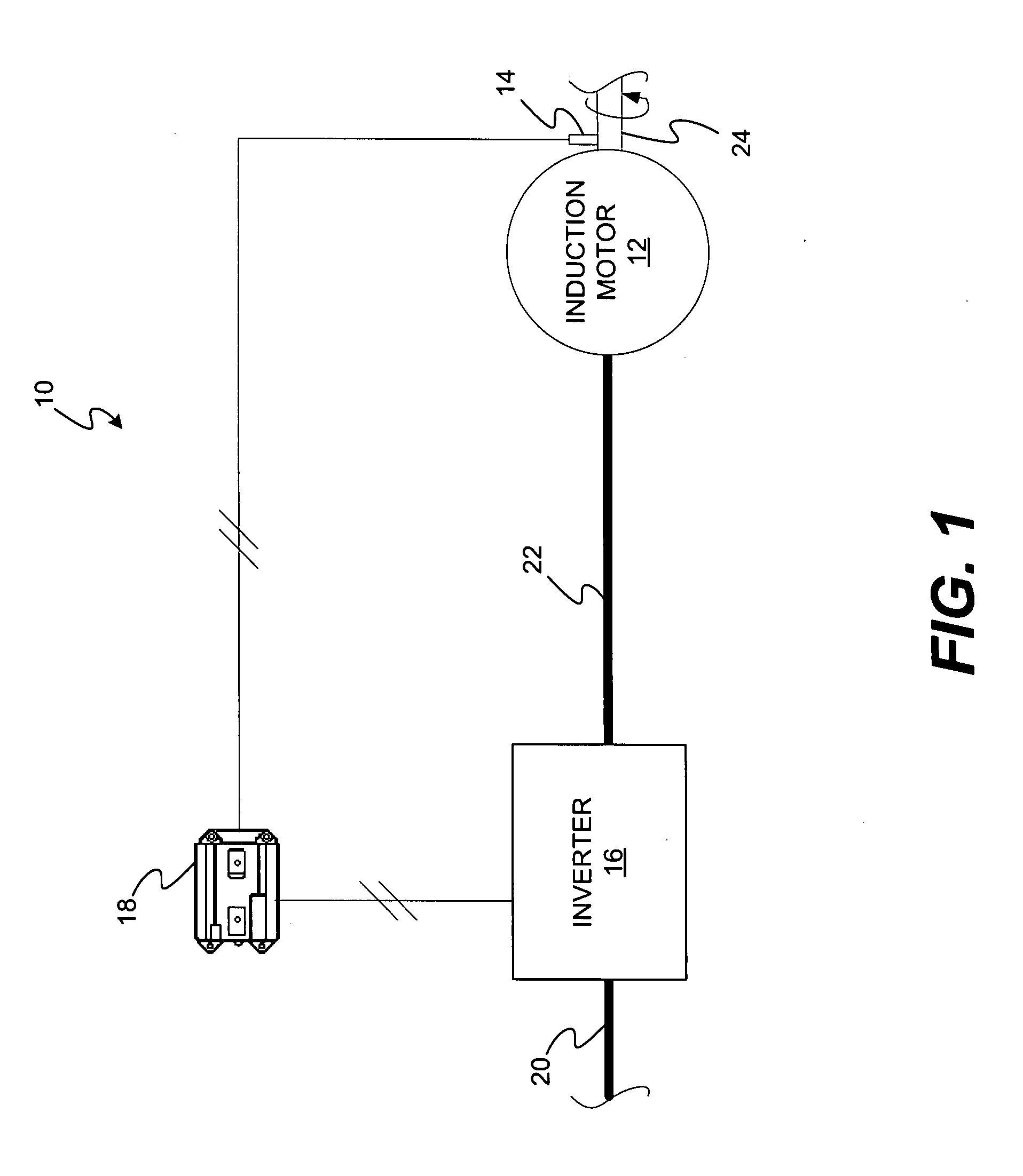
[0015]FIG. 1 illustrates a field weakening control system 10 having an induction motor 12, a sensing device 14, an inverter 16, and a controller 18. Field weakening control system 10 may generally receive a direct current (“DC”) signal from a DC bus 20, convert the DC signal to one or more voltages, and produce one or more AC currents to drive a mechanical output of induction motor 12. The mechanical output of induction motor 12 may be at least partially controlled by inverter 16 and controller 18. As such, field weakening control system 10 may be associated with and / or included in a machine that is driven by a mechanical output of induction motor 12. For example, the mechanical output of induction motor 12 may drive a traction device, a wind tunnel, a pipeline compressor, a washing machine, a dishwasher, a standalone fan, and / or a record player.

[0016]Induction motor 12 may be generally operable to receive one or more alternating current (“AC”) signals from an AC bus 22 and use them...


PUM


Abstract

A field weakening control system for use with an induction motor is disclosed. The field weakening control system has a sensing device configured to generate a signal indicative of a speed of the induction motor and a controller. The controller is configured to determine an initial voltage command based on the signal and determine an acceleration of the induction motor based on the signal. The controller is also configured to generate a desired voltage command based on at least one of the initial voltage command and the acceleration.

Description

TECHNICAL FIELD[0001]The present disclosure is directed to dynamic field weakening and, more particularly, to a system and method for dynamic field weakening in an induction motor.BACKGROUND[0002]Induction motors are used to provide mechanical power in a variety of applications such as, for example, driving traction devices, wind tunnels, pipeline compressors, washing machines, dishwashers, standalone fans, and record players. Induction motors are electrically driven by a current to generate a mechanical torque output. That is, changing currents within components (e.g. field windings) of the induction motor create an electromagnetic flux, and a rotating member of the induction motor is caused to rotate by one or more currents interacting with the magnetic flux (e.g. in accordance with the principle of Lorentz force). The current applied to an induction motor can be regarded as a vector with two components: a torque current component iq, and a flux current component id. By controllin...

Claims


Application Information

Patent Timeline
IPC IPC(8): H02P27/04
CPCH02P23/009H02P23/0036H02P23/0004
Inventor SOPKO, THOMAS MICHAELWAI, JACKSON
Owner CATERPILLAR INC
Why Eureka
Try Eureka