Joining Surface Structure for a Plurality of Cases

Inactive Publication Date: 2008-12-25
TOYOTA JIDOSHA KK
View PDF5 Cites 2 Cited by
  • Summary
  • Abstract
  • Description
  • Claims
  • Application Information

AI Technical Summary

Benefits of technology

[0008]It is an object of the invention to provide a joining surface structure for joining case and that can reduce oil leakage from the case while maintaining strength of the case.
[0010]According to the above aspect, oil leakage from the case is reduced by the plurality of grooves formed such that the mirror images of the grooves in each joining surface intersect with the grooves in the opposite joining surface, and any given line that connects an inside and an outside of the case intersects with the grooves in the joining surfaces. Oil leakage is also reduced by the sealing material that is filled in the plurality of grooves. The plurality of grooves connect with each other and form a continuous groove, whereby each groove can be made small. In addition, grooves can be formed around the tightening structure. Accordingly, oil leakage from the case can be reduced while strength of the case is maintained.
[0011]In the above aspect, the grooves may be formed in one of the joining surfaces that face each other. With this structure, the grooves are formed in one of the joining surfaces that face each other, thus allowing the case to be processed and oil leakage reduced using a simpler method.
[0012]In the above aspect, the grooves may be formed to spread across the entire joining surface. With this structure, oil leakage is reduced across the entire joining surface, whereby oil leakage is reduced more effectively.
[0013]In the above aspect, the tightening structure may be formed at the center of the joining surfaces between the inner peripheral surface and the outer peripheral surface of the case. With this structure, the pressure applied to a sealing material can be evenly dispersed to the inside and the outside of the case. Therefore, oil leakage can be reduced more effectively.

Problems solved by technology

However, it is difficult to form the groove 1b in the vicinity of the bolt holes 1c because this has a detrimental impact on the strength of the case.
In this case, however, the pressure applied to the sealing material 2 cannot be evenly dispersed to the outer side and the inner side of the case.
As a result, oil is still likely to leak from the joining portion of the case.

Method used


Image

  • Joining Surface Structure for a Plurality of Cases
  • Joining Surface Structure for a Plurality of Cases
  • Joining Surface Structure for a Plurality of Cases

Examples


first embodiment

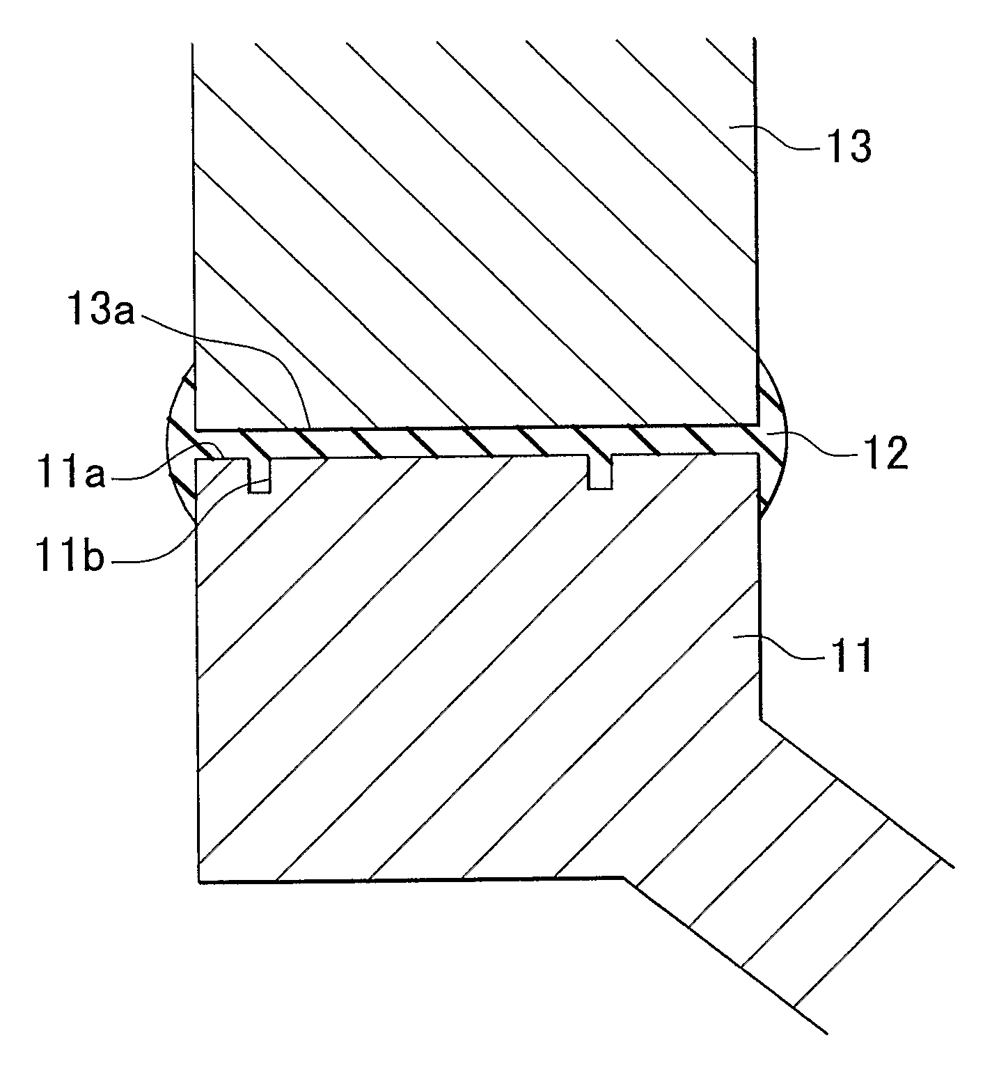
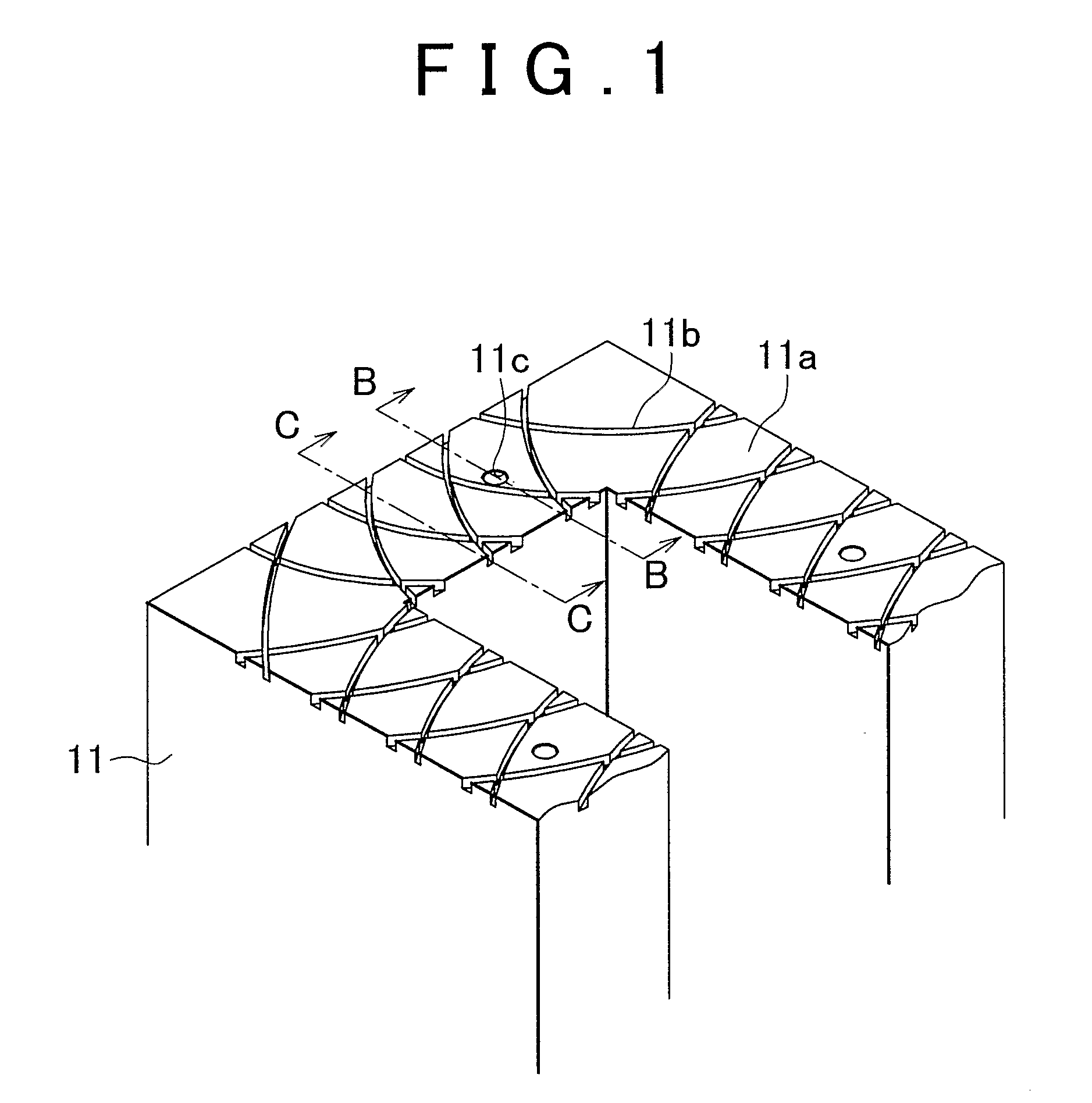
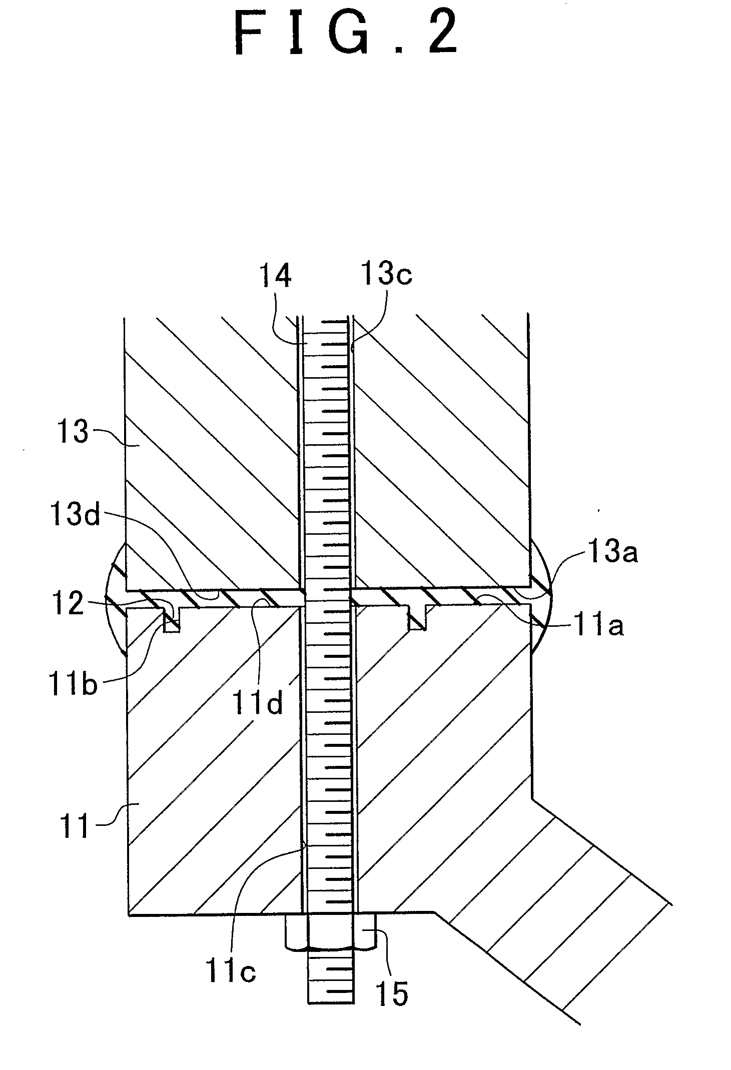
[0025]Hereinafter, a first embodiment of a joining surface structure to which the invention is applied will be described with reference to FIGS. 1 to 4. A joining surface 1a of a lower case 11 is shown in FIG. 1. The joining surface 11a of the lower case 1 is provided with a plurality of grooves 11b and bolt holes 11c. The plurality of grooves 11b are formed with a substantially arced shape and intersect with each other. The bolt holes 11c are used for tightening. The grooves 11b are formed to spread across the entire joining surface 11a, and are processed by cutting the upper surface of the joining surface 11a using a roller. The bolt holes 11c are formed at the center of the lower case 11 between the inner peripheral surface and the outer peripheral surface. A liquid gasket 12 is applied on the grooves 11b as a sealing material, and the lower case 11 is tightened to an upper case 13 using a bolt 14 and a nut 15. Accordingly, the liquid gasket 12 naturally dries and solidifies, whe...

second embodiment

[0036]Next, a second embodiment of a joining surface structure to which the invention is applied will be described with reference to FIGS. 5 and 6. A joining surface 21a of a lower case 21 is shown in FIG. 5. The joining surface 21a of the lower case 21 is provided with a plurality of grooves 21c and bolt holes 21c. The plurality of grooves 21c are formed with a substantially arced shape. The bolt holes 21c are used for tightening. In contrast to the first embodiment, the grooves 21b are not formed to intersect with each other. However, a joining surface 23a of an upper case 23 is provided with a plurality of grooves 23b and bolt holes 23c. The plurality of grooves 23b are formed with a substantially arced shape. The bolt holes 23c are used for tightening. The grooves 23b are also not formed to intersect with each other. In addition, the grooves 21b and the grooves 23b are formed to spread across the entire joining surfaces. The grooves 21b and the grooves 23b are processed by cutti...


PUM


Abstract

A joining surface of a lower case including a plurality of grooves and bolt holes. The plurality of grooves are formed with a substantially arced shape and intersect with each other. The bolt holes are used for tightening. The grooves intersect with each other, and connecting sections of the grooves form a continuous groove that separates the inside of the case from the outside of the case. A liquid gasket is filled in the grooves.

Description

BACKGROUND OF THE INVENTION[0001]1. Field of the Invention[0002]The invention relates to a joining surface structure that joins a plurality of cases that form a transmission case, an oil pan or the like.[0003]2. Description of the Related Art[0004]Conventionally, a transmission case and an oil pan for a vehicle are formed by aligning joining surfaces of a plurality of cases to face each other and then tightening the cases by a tightening means such as a bolt and nut. The transmission case and oil pan also function as a tank for holding lubricating oil, hydraulic oil and the like. A gasket is disposed between the joining surfaces of the cases to seal the joining surfaces, thereby preventing oil from leaking out from the cases. For example, Japanese Patent Application Publication No. JP-A-2002-213616 describes a structure in which a liquid gasket is applied to the joining surfaces of the cases to prevent oil leaking out from the cases.[0005]FIGS. 9 to 11 illustrate the structure of th...

Claims


Application Information

Patent Timeline
IPC IPC(8): F16J15/02
CPCF01M2011/0062F16J15/062F16J15/14
Inventor TANIGUCHI, MAKOTO
Owner TOYOTA JIDOSHA KK
Why Eureka
Try Eureka