Seal assembly and method for reducing aircraft engine oil leakage

a technology of aircraft engine and seal, which is applied in the direction of liquid fuel engines, machines/engines, mechanical equipment, etc., can solve the problems of seal leakage and aerosolization of oil, and achieve the effect of reducing oil leakag

Active Publication Date: 2021-02-23
THE BOEING CO
View PDF12 Cites 1 Cited by
  • Summary
  • Abstract
  • Description
  • Claims
  • Application Information

AI Technical Summary

Benefits of technology

[0004]The embodiments disclosed provide a method for reducing oil leakage into bleed air wherein an oil chamber is sealed with a first seal to maintain a first pressure. A ventilating cavity surrounding the oil chamber is sealed with a second seal configured to maintain a second pressure. A suction conduit connected between the ventilating cavity and a pressure reducing device maintains the second pressure less than the first pressure and less than an ambient pressure of the primary air flow path. Oil leaking through the first seal is drawn into the ventilating cavity and air leaking through the second seal is also drawn into the ventilating cavity. The ventilating cavity is exhausted through the pressure reducing device to an external outlet.

Problems solved by technology

However, in operation the seals may leak as the engine wears or the seals may fail.
Since the bearings and oil seals are pressurized, there is a potential to aerosolize the oil that is not contained by the leaking seals, into the compressor air stream.

Method used


Image

  • Seal assembly and method for reducing aircraft engine oil leakage
  • Seal assembly and method for reducing aircraft engine oil leakage
  • Seal assembly and method for reducing aircraft engine oil leakage

Examples


Embodiment Construction

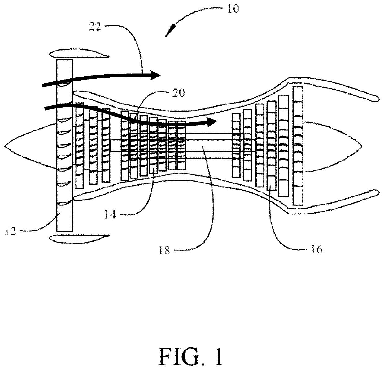
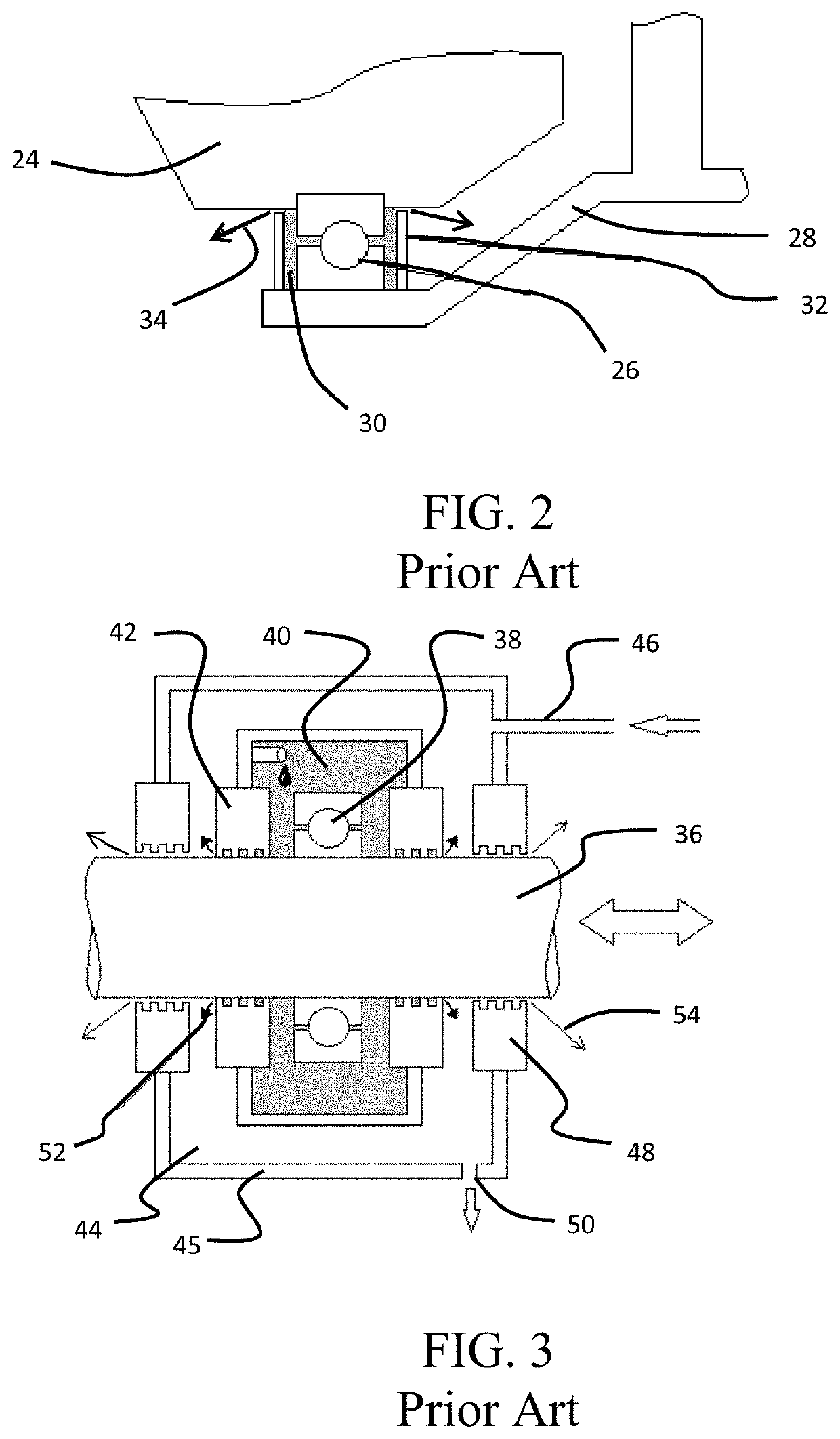
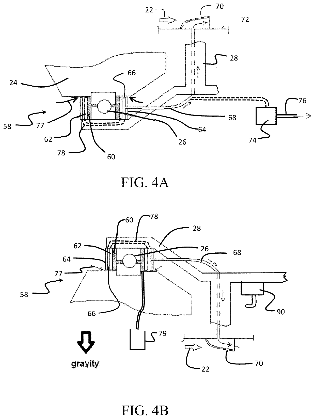
[0013]The embodiments and methods described herein provide a dual labyrinth seal assembly for a gas turbine engine. The first seal defines an inner cavity that surrounds a bearing such as the forward compressor bearing. A second seal defines an outer cavity that surrounds the inner cavity. In operation, any oil leakage that occurs as a result of leakage around the first labyrinth seal is transmitted into the cavity defined by the second labyrinth seal. A vacuum system creates a vacuum within the second cavity such that any oil that is within the second cavity is extracted and then sent overboard via the fan airstream. The vacuum system includes connection to the outer cavity in a first embodiment with an evacuation tube or channel that is formed integrally with or integrated into static structural elements of the engine such as the front compressor frame for the exemplary compressor bearing. The vacuum system also includes low pressure sink such as a scupper connected to the evacuat...


PUM


Abstract

A seal assembly for a gas turbine engine employs a first seal forming an oil chamber around a bearing. The first seal is configured to maintain the oil chamber at a first pressure. A second seal forms a ventilating cavity around the oil chamber. The second seal is configured to maintain the ventilating cavity at a second pressure, the second pressure being less than the first pressure and less than an ambient pressure of a primary flow path in the engine. A pressure reducing device is coupled to the ventilating cavity. The pressure reducing device is configured to maintain the second pressure.

Description

BACKGROUND INFORMATIONField[0001]Embodiments of the disclosure relate generally to lubrication of bearings in aircraft engines and more particularly to pressure control and routing of leaking oil to an overboard location out of the engine compressor flow.Background[0002]Gas turbine engines include pressurized oil bearings that support the rotating fan, compressor and turbine shafts. Specifically, the bearings support the rotating segments within the stationary segments. The gas turbine engines also include various oil seals surrounding the bearings to prevent oil leakage. However, in operation the seals may leak as the engine wears or the seals may fail. Since the bearings and oil seals are pressurized, there is a potential to aerosolize the oil that is not contained by the leaking seals, into the compressor air stream. As the compressor air stream may be used for various purposes on the aircraft, it is desirable to prevent aerosolized oil from being introduced into the aircraft in ...

Claims


Application Information

Patent Timeline
Patent Type & Authority Patents(United States)
IPC IPC(8): F04D29/08F01D25/18F04D27/00F04D29/056F04D29/063F04D29/52
CPCF04D29/083F01D25/183F04D27/009F04D29/056F04D29/063F04D29/522F05D2260/609
Inventor LIN, CHAO-HSINHORSTMAN, RAYMOND H.BATES, III, GEORGE
Owner THE BOEING CO
Why Eureka
Try Eureka