Rotary shaft link assembly structure

a technology of assembly structure and rotary shaft, which is applied in the direction of wing accessories, portable computer details, instruments, etc., can solve the problems of poor operation smoothness, limited rotational freeness of pivot shaft units disposed near the same central line, and unsatisfactory coordination between the rotary shafts. , to achieve the effect of reducing powder droppage and oil leakag

Active Publication Date: 2021-07-01
FIRST DOME
View PDF0 Cites 1 Cited by
  • Summary
  • Abstract
  • Description
  • Claims
  • Application Information

AI Technical Summary

Benefits of technology

[0008]It is therefore a primary object of the present invention to provide a rotary shaft link assembly structure is connected between a first support and a second support of two articles. The rotary shaft link assembly structure has a rotary shaft assembly and at least one synchronous rotational assembly. The rotary shaft assembly has multiple connection members side-by-side arranged. Each connection member is formed with at least one hollow section in the sideward direction. The synchronous rotational assembly passes through the hollow sections of the connection members to respectively connect with the first and second supports, whereby the connection members are transversely serially connected to drivingly bend and connect along with the synchronous rotational assembly. The connection members respectively shield a part of the synchronous rotational assembly to provide a protection effect and reduce the dropped powder and oil leakage caused by the friction when the synchronous rotational assembly is rotated.

Problems solved by technology

Therefore, when operating and turning open the display module or the apparatus body module, the coordination between the rotary shafts is not idealistic.
Also, the rotational freeness of the pivot shaft units disposed near the same central line is limited.
As a result, in both the opening and closing rotation process of the entire electronic apparatus, the smoothness of operation is poorer.
However, in practical application, when the two modules pivotally connected with each other are closed or opened, the connection sections of the respective rotary shaft assemblies will abrade each other to cause dropped powder and oil leakage.
As a result, in use, the dropped powder and leaking oil often directly contaminate the environment.

Method used


Image

  • Rotary shaft link assembly structure
  • Rotary shaft link assembly structure
  • Rotary shaft link assembly structure

Examples


Embodiment Construction

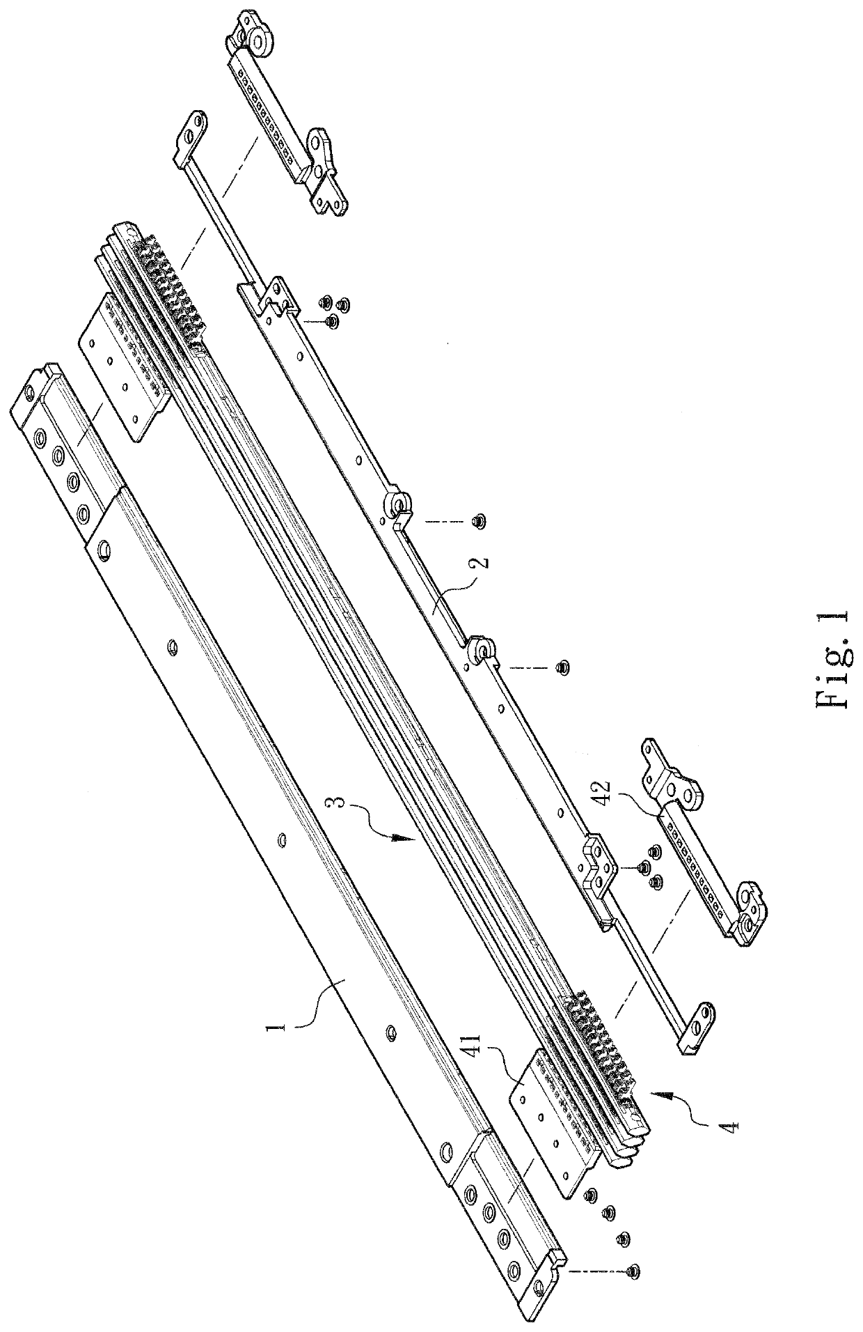
[0025]Please refer to FIGS. 1 to 4. The rotary shaft link assembly structure of the present invention includes a first support 1, a second support 2, a rotary shaft assembly 3 and a synchronous rotational assembly 4. The first support 1 is connected with a first article (not shown, can be a section of an electronic device). The second support 2 is connected with a second article (not shown, can be another section of the electronic device).

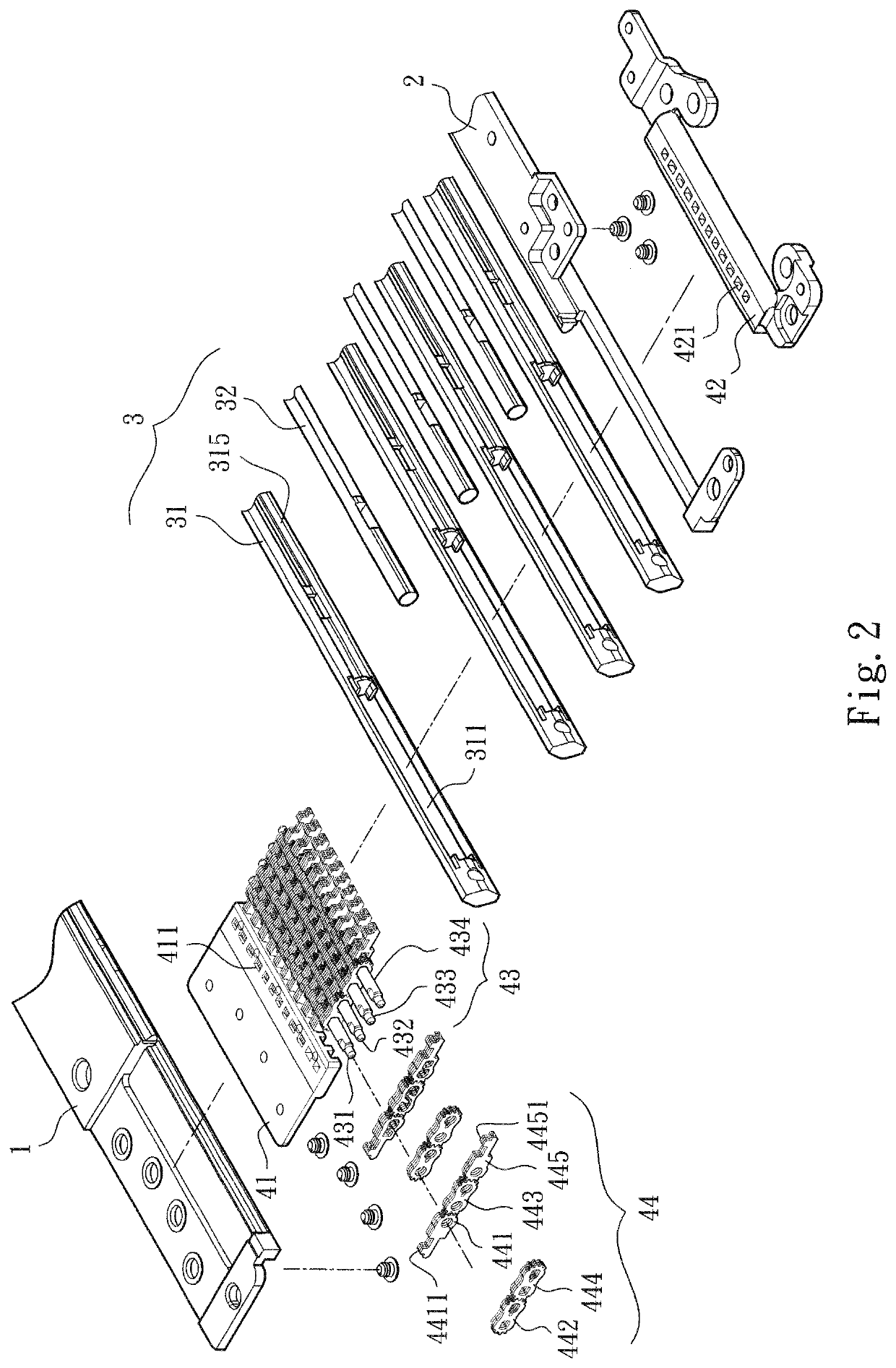
[0026]The rotary shaft assembly 3 is composed of multiple connection members 31 and multiple spacer shaft rods 32. The connection members 31 are side-by-side arranged between the first and second supports 1, 2. Each connection member 31 is correspondingly formed with at least one hollow section 311. Each connection member 31 has two arched channels 315 respectively formed on two sides of the opening of the hollow section 311.

[0027]The spacer shaft rods 32 are respectively attached to and sandwiched between the connection members 31. In a preferred ...


PUM


Abstract

A rotary shaft link assembly structure is connected between a first support and a second support of two articles. The rotary shaft link assembly structure has a rotary shaft assembly and at least one synchronous rotational assembly. The rotary shaft assembly has multiple connection members side-by-side disposed between the first and second supports. Each connection member is correspondingly formed with at least one hollow section. The synchronous rotational assembly passes through the hollow sections of the connection members to respectively connect with the first and second supports, whereby the connection members are transversely serially connected to drivingly bend and connect along with the synchronous rotational assembly. The connection members respectively shield a part of the synchronous rotational assembly to provide a protection effect and reduce the dropped powder and oil leakage caused by the friction.

Description

BACKGROUND OF THE INVENTION1. Field of the Invention[0001]The present invention relates generally to a rotary shaft link assembly structure, and more particularly to a rotary shaft link assembly structure, in which the rotary shaft assembly can partially shield the connection sections of the synchronous rotational assembly to provide a protection effect and reduce the dropped powder and oil leakage.2. Description of the Related Art[0002]There are various electronic devices provided with upper covers or display screens, (such as mobile phones, notebooks, PDA and electronic books). The upper covers or display screens are pivotally assembled on the electronic devices via pivot pins or rotary shafts, whereby the upper covers or the display screens can be reciprocally rotated and opened / closed under external force. For example, Taiwanese Patent No. 97222022 “rotary shaft structure” and Taiwanese Patent No. 98207366 “pivot pin structure” provide typical embodiments.[0003]In order to use t...

Claims


Application Information

Patent Timeline
Patent Type & Authority Applications(United States)
IPC IPC(8): G06F1/16
CPCG06F1/1681E05D3/14G06F1/1616E05Y2900/606
Inventor HSU, AN SZU
Owner FIRST DOME
Why Eureka
Try Eureka