Combined oil ring

a technology of oil rings and oil rings, applied in the direction of brake systems, machines/engines, transportation and packaging, etc., can solve the problems of particularly drastic oil loss phenomenon, and oil loss occurring, so as to reduce oil leakage from the gap, reduce oil consumption, and reduce the effect of mass

Inactive Publication Date: 2009-11-05
TEIKOKU PISTON RING CO LTD
View PDF11 Cites 1 Cited by
  • Summary
  • Abstract
  • Description
  • Claims
  • Application Information

AI Technical Summary

Benefits of technology

[0014]The present invention uses the side rail capable of closing the gap of the oil ring and therefore can reduce oil leakage from the gap and lower oil consumption. Moreover, the side rail can possess a smaller mass than the oil ring, and compared to the coil expander can possess a smaller outward force on the surface of the cylinder bore. Therefore, when the piston lowers during engine braking where the combustion chamber reaches a negative pressure, the side rail is raised by the negative pressure and inertial force, and is easily pressed against the upper surface of the ring groove. The side rail consequently closes the clearance between the surface of the cylinder bore and the outer circumferential surface of the piston so that the quantity of oil pumped up into the combustion chamber can be reduced and oil consumption can therefore be smaller. Moreover, oil ring movement is not obstructed because there is no torsion in the side rail along the axial direction of the oil ring. Also, the coil expander does not press the side rail against the upper surface of the ring groove so that there is no interference with oil control functions of the combined oil ring even if deposits such as carbon sludge occur on the upper surface of the ring groove.
[0015]Offsetting the gaps of the oil ring and side rail along the circumference is effective in reducing oil consumption. The gap positions are preferably offset from each other by 180 degrees, and a rotation preventing member may be added to the side rail.
[0016]Setting at least one of gaps of the oil ring and the side rail as an oblique gap along the radius will narrow the oil path of the gap and so is effective in reducing oil consumption. Setting the gaps of the oil ring and the side rail as oblique gaps along the radius and making them face mutually opposite from each other is particularly effective in lowering oil consumption even further. In other words, the oil path through the gap is narrowed and is effective in reducing oil consumption even if the oil ring and / or the side rail rotates during operation and the gap positions align with each other.
[0017]Making the radial thickness of the side rail larger than the radial thickness of the oil ring serves to make the side rail completely close the gap of the oil ring and is therefore effective in lowering oil consumption.
[0018]The sealing with the outer circumference can be improved if the side rail possesses a slight radial pressing force against the cylinder wall. Moreover, the rotation of the side rail can be prevented and therefore aligning with the gap of the oil ring can be prevented. Setting the gap dimensions to 0<L1−L2≦3 mm where L1 is the gap dimension while the side rail is in the free state, and L2 is the gap dimension during assembly of the side rail will prove adequate for providing the side rail with a slight expansive force. A slight expansive force of the side rail increases little friction. The side rail may also be set so that there is no radial pressing force on the cylinder wall.

Problems solved by technology

This oil loss phenomenon is particularly drastic when the gaps of the upper and lower rails are aligned with each other since the combustion chamber reaches a negative pressure during deceleration where there is an engine braking effect.
Also, the sealing on the upper side of the piston ring groove is weak in the combined oil rings with an integrated upper and lower rail structure so that oil loss occurs in the clearance between the upper surface of the ring groove and the upper surface of the oil ring.
This oil loss phenomenon becomes especially drastic during deceleration where engine braking occurs, because the combustion chamber reaches a negative pressure.
The technology disclosed in Japanese Patent Non-examined Publication No. 50-94311 has the problem that the belleville spring restricts the oil ring and impedes the oil ring movement, which is sometimes a factor causing oil consumption to worsen.
Moreover, the side rail on the upper side is pressed against the upper surface of the ring groove so that poor conformability of the upper side rail on the inner circumferential surface of the cylinder due to carbon sludge deposits, as well as wear at the contact portion between the side rail pressing section and the side rail sometimes inhibit the oil control function.

Method used


Image

  • Combined oil ring
  • Combined oil ring
  • Combined oil ring

Examples


Embodiment Construction

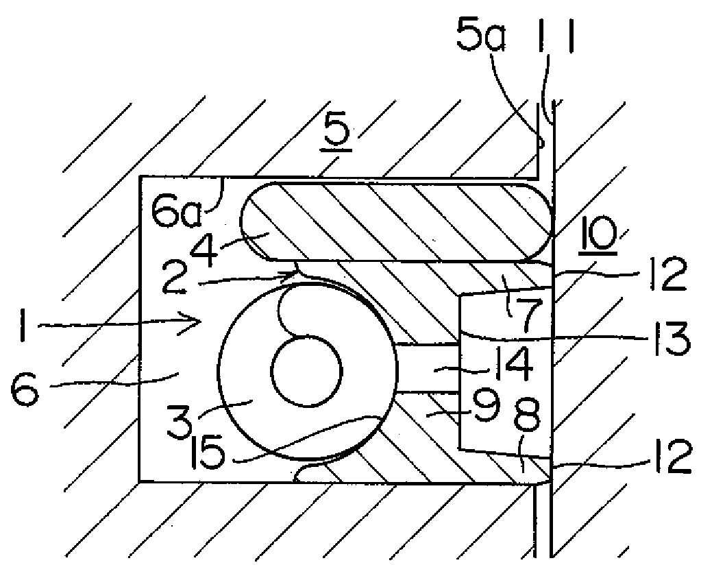
[0025]A combined oil ring 1 is made up of an oil ring 2, a coil expander 3, and a side rail 4. The combined oil ring 1 is mounted on a ring groove 6 of a piston 5.

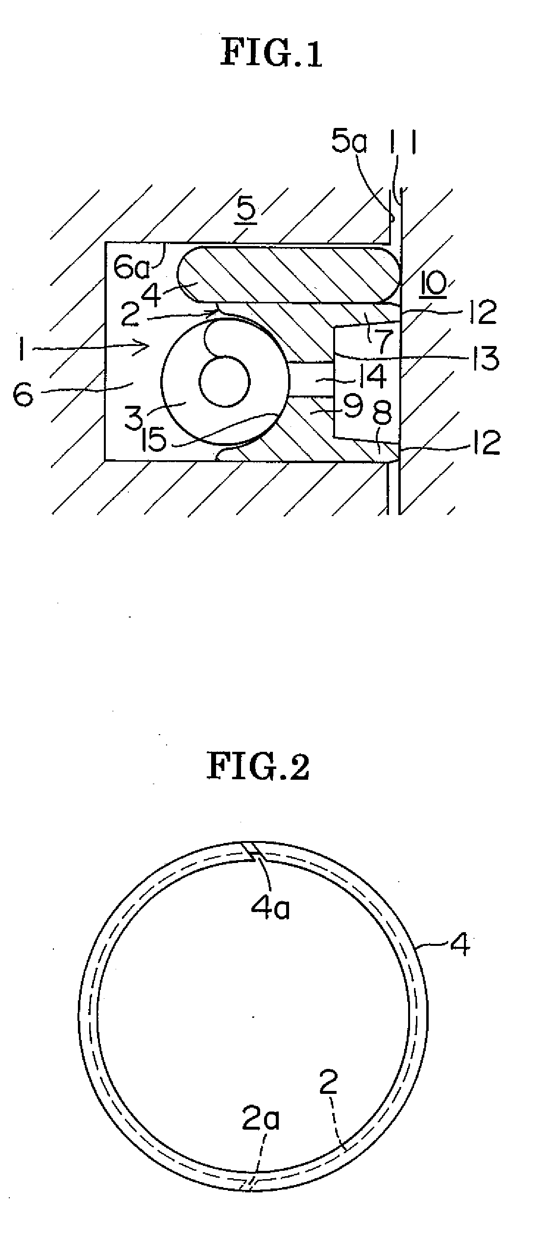
[0026]The oil ring 2 is a steel ring having an approximately I-shaped cross section and including an oblique gap 2a along the radius. The oblique gap 2a along the radius is a gap with a gap shape formed of the opposite end surfaces of the oil ring 2 that are positioned at an angle relative to the normal line of the circle of a cylinder 10 bore inner circumference that contacts the outer circumference of the oil ring 2 when the oil ring 2 is installed in the cylinder 10. The oil ring 2 includes a pair of upper and lower rails 7 and 8 extending along the circumference, and a straight, thin-walled web 9 connecting the pair of upper and lower rails 7 and 8 and extending along the circumference. The outer circumferential surfaces of the upper and lower rails 7 and 8 respectively make up sliding surfaces 12 that contact the inne...


PUM


Abstract

A combined oil ring includes an oil ring having upper and lower rails formed integrally at an outer circumferential side of the oil ring to slide on a cylinder wall; a coil expander installed at an inner circumferential side of the oil ring to force the oil ring radially outwards; and a side rail installed at an upper side of the oil ring and having no torsion along an axial direction of the oil ring.

Description

BACKGROUND OF THE INVENTION[0001]1. Field of the Invention[0002]The present invention relates to a combined oil ring utilized in internal combustion engines, and relates in particular to a combined oil ring with low oil consumption.[0003]2. Description of the Related Art[0004]A compression ring functioning mainly as a gas seal; and an oil control ring functioning mainly to control the thickness of the oil film on the wall surface of the cylinder bore are mounted on a piston in an internal combustion engine. The oil control ring is mainly a steel combined oil ring with a spacer expander and separate upper and lower rails; or a steel combined oil ring with an integrated upper and lower rail structure and having a coil expander. These oil control rings control the thickness of the oil film on the cylinder wall by pressing the rail section against the inner wall surface of the cylinder bore by the expander to scrape off oil on the inner wall surface of the cylinder bore.[0005]In the cas...

Claims


Application Information

Patent Timeline
Patent Type & Authority Applications(United States)
IPC IPC(8): F16J9/06
CPCF16J9/064F16J9/062
Inventor HAYASHI, MASAKI
Owner TEIKOKU PISTON RING CO LTD
Why Eureka
Try Eureka