
Signal transmission cable and multi-wire cable

a transmission cable and multi-wire technology, applied in the direction of insulated conductors, cables, power cables, etc., can solve the problems of affecting the electrical performance of the signal transmission cable, the insulating layer of the inner insulated wire as well as the inner conductor, and the inconvenient use of the four-wire stranded common shield, etc., to achieve excellent electrical characteristics and mechanical characteristics.

Inactive Publication Date: 2008-12-25
HITACHI CABLE +1
View PDF6 Cites 30 Cited by
  • Summary
  • Abstract
  • Description
  • Claims
  • Application Information

AI Technical Summary

Benefits of technology

The present invention provides a signal transmission cable with excellent electric, mechanical, and terminal workability. The cable has multiple inner insulated wires stranded with each other, with an insulating layer mainly composed of a fluorine resin and a skin layer mainly composed of a fluorine resin with color pigments. The cable also has an outer conductor and a sheath layer comprising an insulator. The skin layer may contain titanium oxide and nickel as color pigments. The insulating layers of the inner insulated wires may have different colors. The cable may be made by extrusion molding or wrapping. The cable may be flatly arranged or stranded with each other. The technical effects of the invention are improved signal transmission and durability of the cable.

Problems solved by technology

However, there are following disadvantages in structure of the conventional cable.
Therefore, the four-wire stranded common shield is not suitable for the application of twisting the cable multi-axially, for example, in the portable telephone.
Further, in the conventional cable, there is a problem of the terminal processing, in that it is difficult to conduct the laser beam machining with the use of YAG laser.
Namely, the laser beam transmits through gaps between the strands in the outer conductor, thereby damaging the insulating layer of the inner insulated wires as well as the inner conductor.
On the other hand, when a color other than black is used for the insulating layer, for example, when only one of the insulating layers is colored by black and the other insulating layers are colored by different colors that are distinguishable from black, the insulating layer and the inner conductor of the inner insulated wire having the insulating layer colored by the color other than black will be damaged when the outer conductor is cut by the laser beam machining.
The cable disclosed by JP-A-2004-192815 is not practical, since kind of additives to be added to the resin which is the main material of the insulating layer, combination thereof, and doping amount thereof are not disclosed.

Method used


Image

  • Signal transmission cable and multi-wire cable
  • Signal transmission cable and multi-wire cable
  • Signal transmission cable and multi-wire cable

Examples


first preferred embodiment

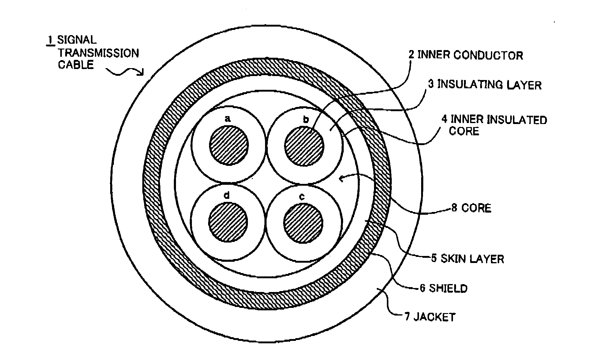
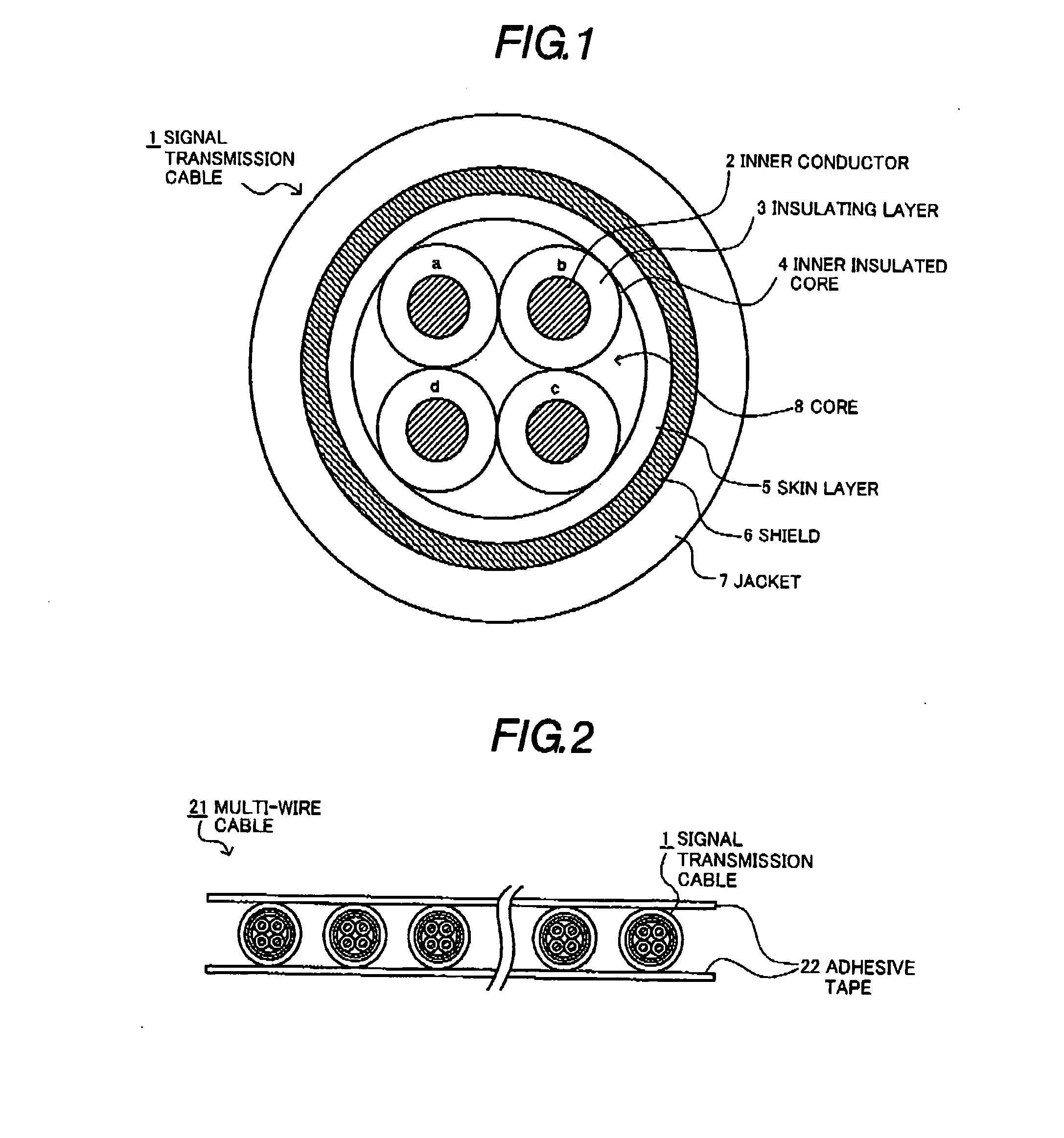
[0062]As shown in FIG. 1, the signal transmission cable 1 in the first preferred embodiment according to the present invention comprises stranded four inner insulated wires 4, each of the inner insulated wires 4 comprising an inner conductor 2, an insulating layer 3 mainly composed of a fluorine resin provided at an outer periphery of the inner conductor 2, a skin layer 5 mainly composed of a fluorine resin and doped with two kinds of additives as color pigment and provided at an outer periphery of the stranded four inner insulated wires 4, an outer conductor (shield) 6 provided at an outer periphery of the skin layer 5, and a sheath layer (jacket) 7 comprising an insulator and provided at an outer periphery of the outer conductor 6.

[0063]Preferably, the inner conductor 2 of the inner insulated wire 4 is formed by stranding a plurality of copper alloy wires or silver-plated copper alloy wires. With considering that the signal transmission cable 1 is put through a hinge part of a not...

second preferred embodiment

[0091]As shown in FIG. 2, a multi-wire cable 21 in the second preferred embodiment according to the present invention comprises a plurality of the signal transmission cables 1 that are flatly arranged. In the multi-wire cable 21, the signal transmission cables 1 are disposed with a predetermined pitch on an adhesive tape 22 and another adhesive tape 22 is disposed on the signal transmission cables 1, to be integrated.

[0092]CO2 laser beam is irradiated at a predetermined position of a sheath layer 7 at a terminal portion of this multi-wire cable 21 to make a notch, and removing a part of the sheath layer 7 at a cut terminal side, to expose a part of the outer conductor 6. YAG laser beam (1064 nm) is irradiated at a predetermined position of an exposed part of the outer conductor 6 to make a notch, and removing a part of the outer conductor 6 and a part of the skin layer 5 at the cut terminal side, to expose a part of the inner insulator 3. The CO2 laser beam is irradiated at a predet...

third preferred embodiment

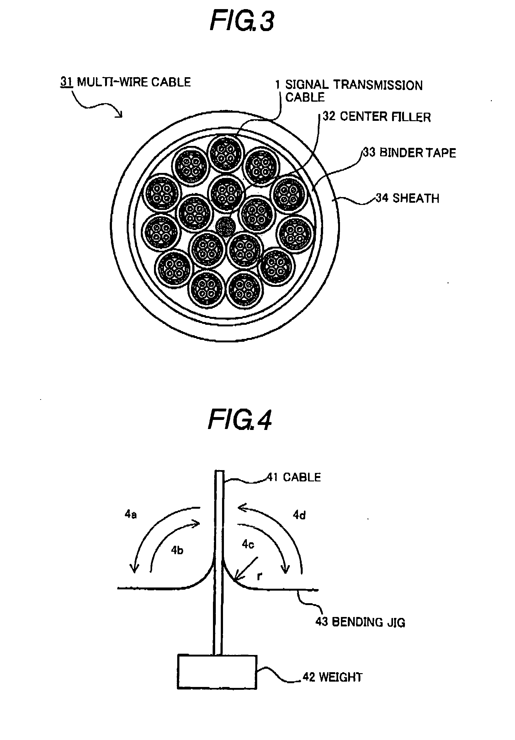
[0093]As shown in FIG. 3, a multi-wire cable 31 in the third preferred embodiment according to the present invention comprises a plurality of the signal transmission cables 1 that are stranded with each other. In the multi-wire cable 31, a plurality (16, for example) of the signal transmission cables 1 are stranded with each other at an outer periphery of a tension member or center filler 16, a binder tape 33 is provided at an outer periphery of the stranded signal transmission cables 1, and a sheath 34 is provide at an outer periphery of the binder tape 33.

[0094]In the multi-wire cables 21, 31, the signal transmission cable 1 incorporated therein is excellent in the electric characteristics and the mechanical characteristics and is suitable for the laser beam machining, so that the multi-wire cables 21, 31 are suitable for signal transmission between the main body and the liquid-crystal display in the small size electronic equipment such as the notebook-sized personal computer, the...


PUM

PropertyMeasurementUnit
thicknessaaaaaaaaaa
thicknessaaaaaaaaaa
thicknessaaaaaaaaaa

Abstract

An insulating layer 3 mainly composed of a fluorine resin is provided at an outer periphery of an inner conductor 2 to provide an inner insulated wire 4. A skin layer 5 mainly composed of a fluorine resin and doped with titanium oxide and carbon black or the titanium oxide and nickel as color pigment is provided at an outer periphery of stranded inner insulated wires 4. An outer conductor (shield) 6 is provided at an outer periphery of the skin layer 5, and a sheath layer (jacket) 7 is provided at an outer periphery of the outer conductor 6, to provide a signal transmission cable 1 having excellent electric characteristics, mechanical characteristics and terminal workability.

Description

[0001]The present application is based on Japanese Patent Application No. 2007-158691 the entire contents of which are incorporated herein by reference.BACKGROUND OF THE INVENTION[0002]1. Field of the Invention[0003]The present invention relates to a signal transmission cable and a multi-wire cable having excellent electric characteristics, mechanical characteristics, and terminal workability.[0004]2. Related Art[0005]As a cable used for signal transmission between a main body and a liquid-crystal display in small-sized electronic devices such as notebook-sized personal computer, portable telephone and the like, a superfine coaxial cable has been used, since predetermined electric characteristics for EMI (Electromagnetic Interference) and SKEW (a clock skew) are required. For example, Japanese Patent Laid-Open No. 2002-352640 (JP-A-2002-352640) discloses an example of the super fine coaxial cables.[0006]As shown in FIG. 9, a superfine coaxial cable 91 comprises an inner conductor 92...

Claims


Application Information

Patent Timeline
Patent Type & Authority Applications(United States)
IPC IPC(8): H01B7/18
CPCH01B7/04H01B7/1875
Inventor HUANG, DETIANKOMURO, HIROSHINAKAGAWA, RYUJINAITO, KAZUYUKIOKIKAWA, HIROSHI
Owner HITACHI CABLE
Learn More