Eureka AIR delivers breakthrough ideas for toughest innovation challenges, trusted by R&D personnel around the world.

Communication Device, Communication System, Communication Method, Communication Program, and Communication Circuit

a communication system and communication circuit technology, applied in the field of communication devices, can solve problems such as unbalanced communication schemes, inability to perform proper communication, interference of infrared, etc., and achieve the effects of high transfer efficiency, high quality, and high transfer efficiency

Active Publication Date: 2008-12-18
SHARP KK
View PDF94 Cites 38 Cited by
  • Summary
  • Abstract
  • Description
  • Claims
  • Application Information

AI Technical Summary

Benefits of technology

[0043]Thus, since detection of an omitted or missing frame or the like and retransmission are possible even with the communication scheme which does not limit the number of frames that can be received or transmitted at once (window size), highly reliable communication is possible. Further, notification of error performed for each set of batch transmission data allows efficient data transmission.
[0046]The communication device is suitable for application in a mobile phone which incorporates the communication device for communication. According to such a mobile phone, communication can be carried out with high quality and / or high transfer efficiency.
[0047]Further, the communication device is suitable for a display device that carries out display in accordance with data received by the communication device. According to such a display device, communication can be carried out with high-quality and / or high transfer efficiency.
[0048]The communication device is suitable for application in a printing device which prints from the data received by the communication device. According to such a printing device, communication can be carried out with high-quality and / or high transfer efficiency.
[0049]Further, the communication device is suitable for a recording device storing data received by the communication device. According to such a recording device, communication can be carried out with high-quality and / or high transfer efficiency.

Problems solved by technology

Therefore, an interference of infrared occurs, when two or more stations within a communication range simultaneously perform transmission.
Accordingly, proper communication can not be performed.
This is called an unbalanced communication scheme.
This may cause deterioration of communication efficiency in the case of transmitting a large volume of data under such a communication condition that no error occurs, because a response frame is transmitted from the secondary station at every window size.
However, the above-mentioned conventional configuration has the following problem.
However, if the communication is performed via communication path whose quality is not so good, using of UI frames for data transmission may deteriorate the communication efficiency.
Further, a conventional IrDA does not support data transmission through one-way communication in which no response is required.

Method used


Image

  • Communication Device, Communication System, Communication Method, Communication Program, and Communication Circuit
  • Communication Device, Communication System, Communication Method, Communication Program, and Communication Circuit
  • Communication Device, Communication System, Communication Method, Communication Program, and Communication Circuit

Examples


embodiment 1

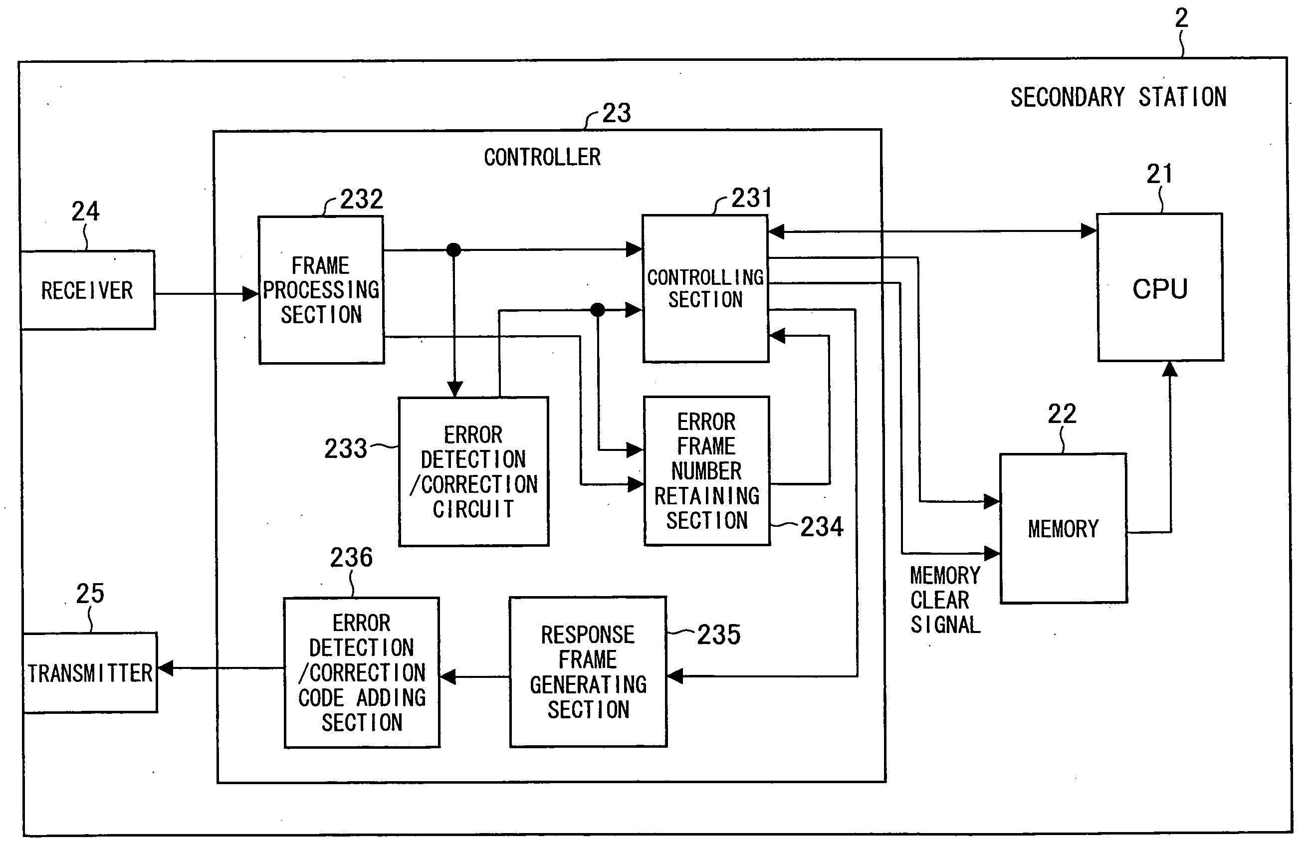
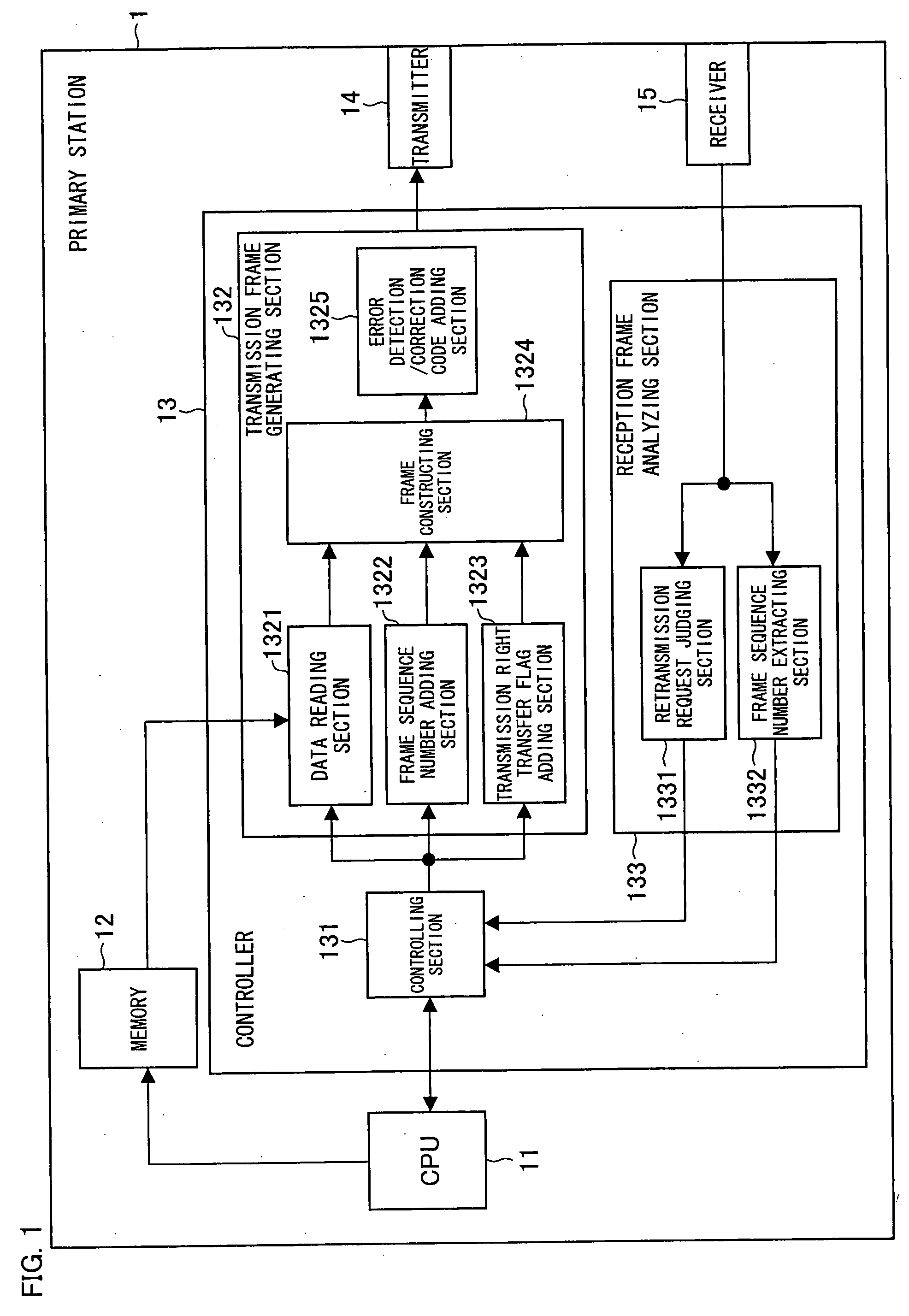
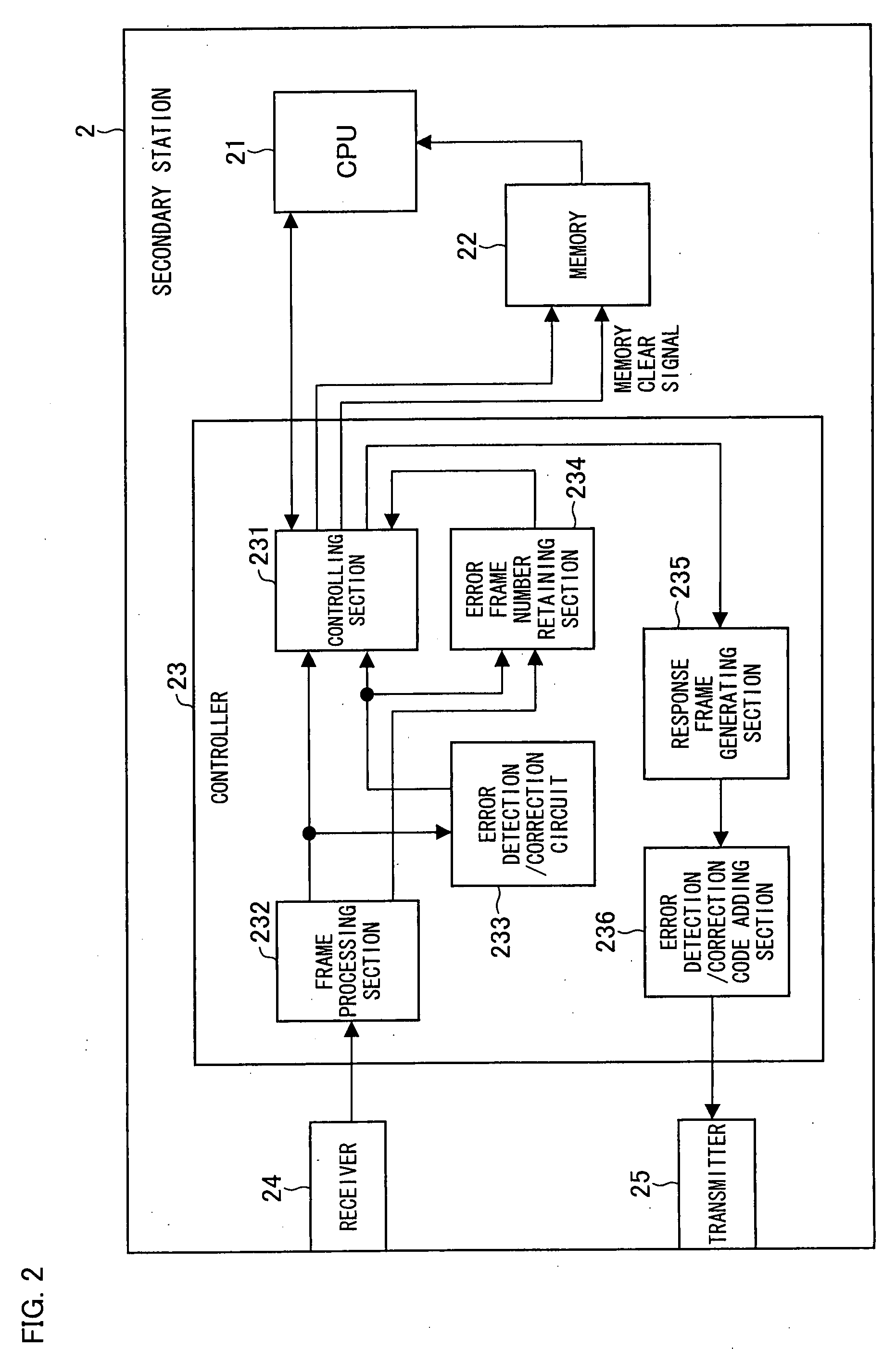
[0420]The following explains a server device (communication device) of a data transferring system (communication system) according to Embodiment 1 of the present invention, with reference to FIG. 1 and FIG. 2. Note that wordings (inclusive of a member and a function) defined in the other embodiments are used in the same manner in the present embodiment, unless otherwise noted.

[0421]FIG. 1 is a block diagram illustrating a structure of a primary station of the present embodiment. As illustrated in FIG. 1, the primary station (transmission device) 1 includes: a CPU 11, a memory 12, a controller 13, a transmitter 14, and a receiver 15.

[0422]The CPU 11 performs a predetermined computation according to a user instruction entered via an operating section (not shown). The predetermined computation can be a transferring process for transferring data. When a transfer instruction of transfer-data is received via the operating section, the CPU 11 stores the transfer-data to be transferred in t...

embodiment 2

[0459]The present embodiment deals with an alternative form of the embodiment 1. Note that wordings (inclusive of a member and a function) defined in the other embodiments are used in the same manner in the present embodiment, unless otherwise noted.

[0460]In the embodiment 1, the primary station transfers the transmission right to the secondary station at every n frames. However, the present embodiment deals with a case where the transmission right is transferred according to an optimum number of the frames which is calculated at the time of establishing connection according to the IrDA communication scheme. This optimum number of the frames is calculated with reference to the numbers of frames that can be transmitted / received from / by the primary station and the secondary station. These numbers of transmittable / receivable frames are provided in a field of a connection request frame transmitted from the primary station and a field of frame transmitted from the secondary station (oppo...

embodiment 3

[0479]A data transferring system (communication system) of embodiment 3 is related to a system which performs communication according to various communication protocols having a hierarchy structure. Note that wordings (inclusive of a member and a function) defined in the other embodiments are used in the same manner in the present embodiment, unless otherwise noted.

[0480]The data transfer system of the present embodiment is described with reference to FIG. 12 to FIG. 17.

[0481]FIG. 12 is a block diagram illustrating a structure of station (i.e. a primary station (transmitting device) or a secondary station (receiving device)) of the present embodiment. Further, FIG. 13 illustrates a protocol stack for a data transmission system of the present embodiment. The function of the present embodiment is realized in a communication protocol layer located in the position of TinyTP layer of the IrDA protocol stack. This protocol layer is hereinafter referred to as SMP (Sequence Management Proto...


PUM


Abstract

In a transmitter (2001), when generating a transmission frame having no limitation to a window size, a batch-transmission-end flag generating circuit (2004) and a sequence number generating circuit (2005) respectively adds a batch-transmission-end flag and a sequence number to the transmission frame. In a receiver, if an omission of a sequence number is detected as a result of analyzing sequence numbers of frames having received from the transmitter (2001), retransmission request is made when receiving a frame whose batch-transmission-end flag indicates the end. In this way, retransmission is possible in data transmission using UI frames, and the communication efficiency can be improved.

Description

TECHNICAL FIELD[0001]The present invention relates to a communication device, a communication system, a communication method, a communication program, and a communication circuit, each of which allows for transmission / reception of data.BACKGROUND ART[0002]In recent years, an infrared communication system is widely used for data exchanging amongst portable electronic devices (mainly amongst personal mobile terminals such as mobile phones, laptop personal computers, electronic notebooks, or the like) or data exchanging between these devices and desktop personal computers or infrared-supporting printers.[0003]Examples of communication schemes adopted in an infrared communication system are IrDA (Infrared Data Association), and ASK (Amplitude Shift Keying), or the like. Of these methods, widely spread in general is IrDA which is a communication protocol for infrared communication. This communication protocol was defined on the basis of HDLC (High-Level Data Link Control) communication s...

Claims


Application Information

Patent Timeline
IPC IPC(8): H04L1/18H04L29/02G06F11/00H04L47/43
CPCH04L1/009H04L1/16
Inventor NAOE, HITOSHIFUKAE, FUMIHIROSAKAI, KOJIOHSAWA, SHOHEI
Owner SHARP KK
Why Eureka
Eureka Blog
Learn More