
Vision Testing System and Method

Active Publication Date: 2008-12-18
CARL ZEISS VISION AUSTRALIA HO
View PDF2 Cites 27 Cited by
  • Summary
  • Abstract
  • Description
  • Claims
  • Application Information

AI Technical Summary

Benefits of technology

[0007]A computer generated environment is also expected to offer additional advantages. For example, a computer based test may allow the test to be conducted over a computer network, such as the Internet. For example, in one embodiment the test may be accessible to the person by activating, at a client computer, an address that links the client computer to a server hosting a computer program containing instructions that are executable by the client, or the server, to conduct the test.

Problems solved by technology

Such test methods are often tedious, requiring the person to make repeated determinations of the clarity of a viewing condition, or to identify symbols.
The process is often conducted under well controlled but restrictive conditions.
Consequently, practitioners can find it difficult to maintain the attention of children in these conditions, impacting on the validity of the results.
In view of the above, existing test methods may not appeal to the person undergoing the test, especially juvenile persons.

Method used


Image

  • Vision Testing System and Method
  • Vision Testing System and Method
  • Vision Testing System and Method

Examples


example 1

[0060]FIG. 3 to FIG. 5 relate to an example of an embodiment of the present invention that displays a sequence of test images such that each test image includes a single test symbol that enlarges over the duration of the sequence. In the present case, each test symbol enlarges incrementally over a range of sizes.

[0061]Referring firstly to FIG. 3, prior to commencement of the test, a pair of image elements (shown here as images of a space craft) including test symbols 302, 304 are displayed to the person undergoing the test. In this example, the pair of test symbols 302, 304 includes an “F” symbol 302 and an “E” symbol 304. Typically, the test symbols 302, 304 will be optotypes, however for clarity purposes they have not be depicted as such in FIG. 3 to FIG. 5.

[0062]In the present case, each test symbol 302, 304 is associated with a respective image element (in this, an image of a “space ship”) to add further interest to the test. It is not essential that the test symbols 302, 304 be...

example 2

[0071]Referring now to FIG. 6 there is shown an example sequence 600 of test images 602, 604, 606 for a test method in accordance with a second embodiment of the present invention.

[0072]In this example, each test image 602, 604, 606 from the sequence 600 of test images includes plural test symbols 608. The person undergoing the test is required to activate the control 108 (ref. FIG. 1) in response to recognising test symbols in the set of test symbols 608 that replicate the shape of a target test symbol 610. In this case, the target symbol 610 is identified to the person throughout the duration of the sequence 600.

[0073]As depicted, in this example each of the test symbols 508 has a particular size from a predetermined range of sizes Sk (where k=1 . . . n). Each size in the predetermined range of sizes has a predetermined relationship with a vision metric.

[0074]The size of the test symbols replicating the target symbol varies throughout the test so that any one of the test symbols r...

example 3

[0084]FIG. 10 and FIG. 11 depict example sequences of test images for a test method in accordance with a third embodiment of the present invention.

[0085]Turning initially to FIG. 10, there is shown a sequence 1000 including test images 1002, 1004, 1006. Each test image 1002, 1004, 1006 includes an arrangement of plural test symbols 1008. In the depicted arrangement includes plural sets of test symbols of equal angular size which, in the present case, are arranged as concentric rings. Each set includes test symbols having a size that is different to the size of the other sets.

[0086]During a test, the person is required to recognise, in a set-by-set manner, a test symbol from within each set that replicates the shape of a target symbol. In the present example the target symbol 1010 is displayed in each test image. In order to indicate recognition of a test symbol 1012, the person aligns the displayed target symbol 1010 with the test symbol replicating the target symbol and then activa...


PUM


Abstract

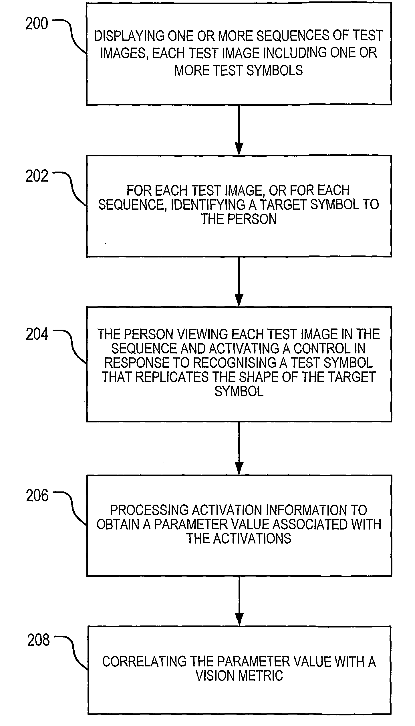
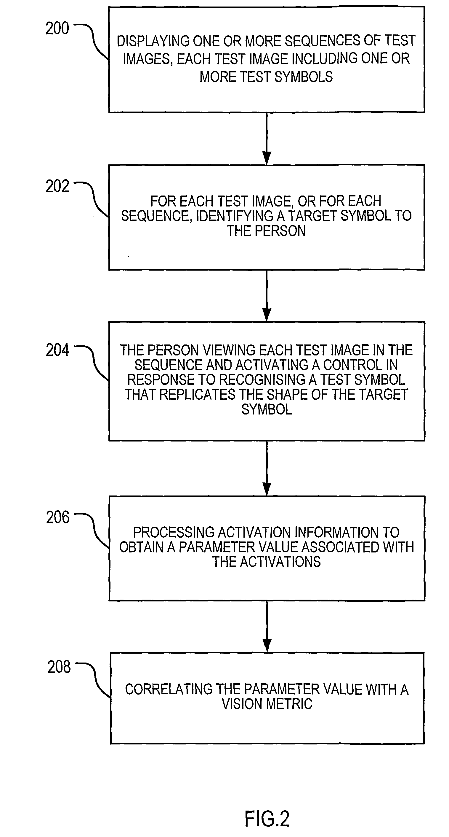
A method for testing a person's vision is disclosed. The method includes providing, for display to the person, one or more sequences of test images, each test image including one or more test symbols. For each test image, a target symbol is identified to the person. The person then views each test image in the sequence and activates a control in response to recognising a test symbol that replicates the shape of the target symbol. At the completion of the sequence, a parameter value associated with the activations is processed and correlated with a vision metric. A system for testing a person's vision is also disclosed.

Description

[0001]This application claims priority from Australian Provisional Patent Application No. 2005906336 filed on 15 Nov. 2005, the contents of which are to be taken as incorporated herein by this reference.FIELD OF THE INVENTION[0002]The present invention relates to vision testing. In a typical application, the present invention may be used to assess a person's visual acuity.BACKGROUND OF THE INVENTION[0003]Conventional vision testing involves reading charts, looking at light sources, or making decisions as to where or what highly simplified stimuli are. Such test methods are often tedious, requiring the person to make repeated determinations of the clarity of a viewing condition, or to identify symbols. The process is often conducted under well controlled but restrictive conditions. Consequently, practitioners can find it difficult to maintain the attention of children in these conditions, impacting on the validity of the results.[0004]In view of the above, existing test methods may n...

Claims


Application Information

Patent Timeline
IPC IPC(8): A61B3/032
CPCA61B3/032A61B3/0041A61B3/028
Inventor FISHER, SCOTT WARRENFREELAND, WARWICK
Owner CARL ZEISS VISION AUSTRALIA HO
Learn More