
Transaxle

Inactive Publication Date: 2008-12-18
KANZAKI KOKYUKOKI MFG
View PDF6 Cites 7 Cited by
  • Summary
  • Abstract
  • Description
  • Claims
  • Application Information

AI Technical Summary

Benefits of technology

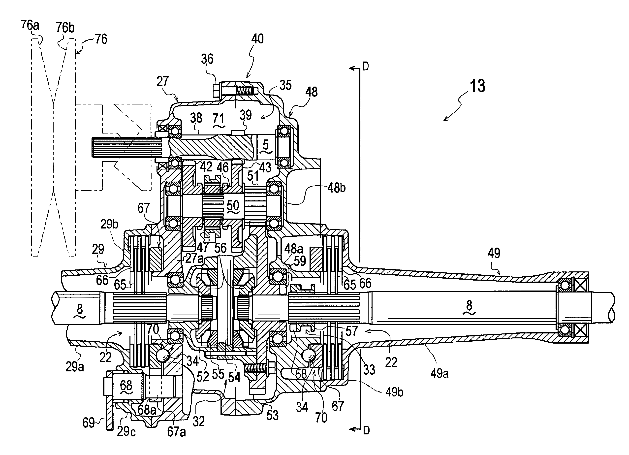
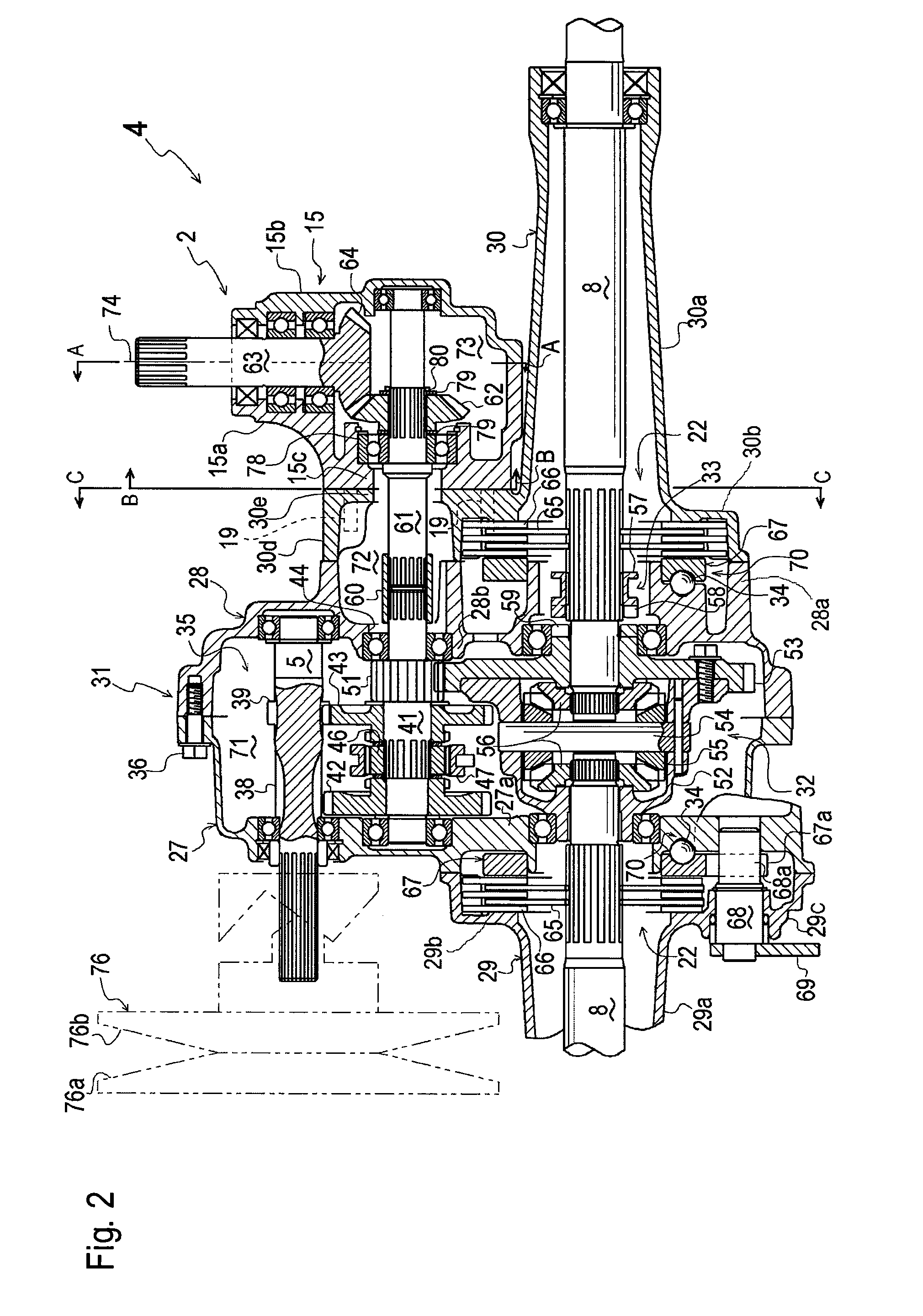
[0009]Therefore, the second divisional housing member incorporating the axle and the brake device also serves as a part for mounting the power take-off device and passing the connection shaft interposed between the transmission and the power take-off device without interference with the brake device, thereby reducing the number of divisional members of the transaxle housing, reducing the number of processes for assembling the transaxle housing, and reducing costs of the transaxle housing.
[0011]Therefore, the power take-off device is mounted to the transaxle housing so as to be prevented from interfering with the second transmission, such as a continuously variable belt transmission.
[0013]Therefore, only by dividing the power take-off casing, the power take-off shaft and connection shaft with the gear train are easily exposed or are easily made to be visible. Thus, a backlash between gears of the gear train can be easily adjusted by adjusting shims or by another means, so as to optimize the power transmission efficiency of the gear train and prolong the life of gears.
[0015]Therefore, the power take-off casing has no outwardly expanded portion like a flange to be fastened by a fastener, thereby being improved in external appearance, and ensuring compactness of the transaxle with the power take-off device.

Problems solved by technology

In this way, the conventional transaxle housing expensively includes many divisional components, and requires many processes to be attached to the PTO device, thereby being disadvantageous in assembility and maintenancability.
If the adjustment is wrong, the gears cause noise and vibration increasing power loss.
However, the PTO casing of the above conventional transaxle is dividable along a dividing surface intersecting the PTO shaft, and even if the PTO casing is divided into divisional parts, the gear in one of the divisional parts is not exposed or not viewable from the outside, thereby inhibiting the gears from being easily treated.

Method used


Image

  • Transaxle
  • Transaxle
  • Transaxle

Examples


Embodiment Construction

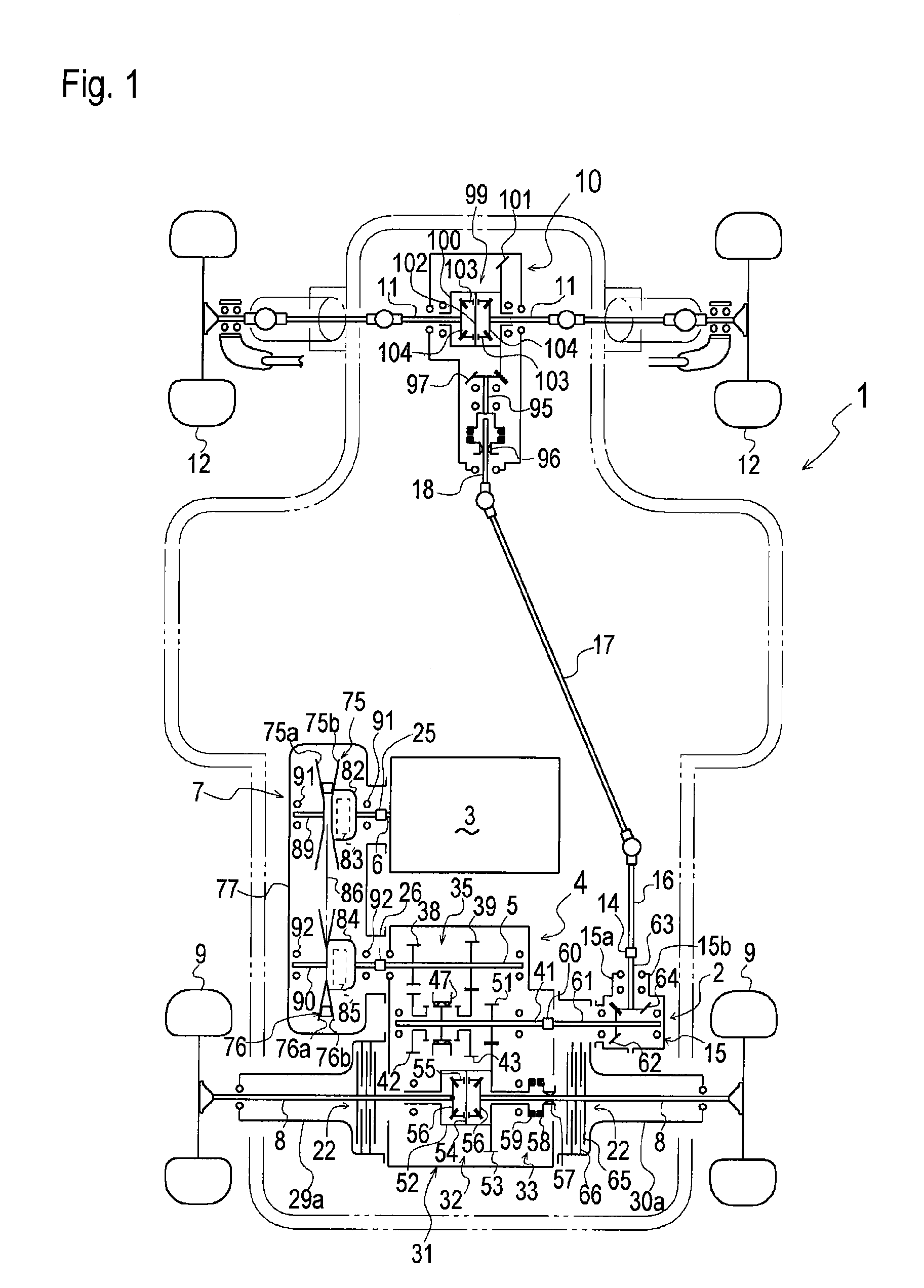
[0024]An entire structure of a four-wheel drive vehicle 1 including a rear transaxle 4 according to an embodiment will be described with reference to FIG. 1. Vehicle 1 is provided at a front portion thereof with a front transaxle 10 supporting left and right front axles 11, and at a rear portion thereof with rear transaxle 4 supporting left and right rear axles 8.

[0025]Left and right front wheels 12 are supported on outer ends of front axles 11, and left and right rear wheels 9 are supported on outer ends of rear axles 8, respectively. Left and right front wheels 12 are steerable wheels to be steered by a steering operation device, such as a steering wheel, provided in vehicle 1.

[0026]An engine 3 having an output shaft 6 is mounted in vehicle 1 between front and rear transaxles 10 and 4. In this embodiment, output shaft 6 projects horizontally leftward from engine 3.

[0027]Rear transaxle 4 includes a transaxle housing 31 supporting left and right rear axles 8 and incorporating a sub ...


PUM


Abstract

In a transaxle, a transaxle housing includes a first divisional housing member and a second divisional housing member joined to each other. A transmission is disposed in the first divisional housing member. An axle is disposed in the mutually joined first and second divisional housing members and drivingly connected to the transmission in the first divisional housing member. A brake device is provided on the axle. The second divisional housing member is formed integrally with a brake chamber portion joined to the first divisional housing member so as to incorporate the brake device in the brake chamber portion. The transaxle is provided with a power take-off device for taking off power from the transmission, including a power take-off casing. A connection shaft is interposed between the transmission and the power take-off device. The second divisional housing member is formed integrally with a mount portion expanded from the brake chamber portion radially with respect to the axle. The power take-off casing is mounted onto the mount portion. The connection shaft is passed through the mount portion between the first divisional housing member and the power take-off casing.

Description

BACKGROUND OF THE INVENTION[0001]1. Field of the Invention[0002]The present invention relates to a transaxle comprising a transaxle housing, in which a transmission, an axle driven by the transmission, and a considerably large brake device, such as a wet brake, provided on the axle are disposed, and a power take-off device mounted on a side of the transaxle housing so as to take off power from the transmission.[0003]2. Related Art[0004]As disclosed in JP 2000-38042 A, there is a well-known conventional transaxle whose transaxle housing comprises a plurality of divisional housing members, that is, a pair of left and right mutually joined main housing halves, a pair of left and right axle casings containing respective axles, and a pair of intermediate casings each of which covers a space between the axle casing and the main housing half. The transaxle includes a power take-off device (hereinafter, referred to as “PTO device”) disposed on a side of the transaxle housing, and includes a...

Claims


Application Information

Patent Timeline
IPC IPC(8): B60K17/16B60K17/06B60K17/344F16H57/023
CPCB60K17/08B60K17/34B60Y2200/221F16H57/023F16H57/037F16H2057/02026F16H2057/02056
Inventor NISHIMOTO, SHUJI
Owner KANZAKI KOKYUKOKI MFG
Learn More