
Positionable back draft assembly

Inactive Publication Date: 2008-12-11
ROBOVENT PROD GRP
View PDF16 Cites 40 Cited by
  • Summary
  • Abstract
  • Description
  • Claims
  • Application Information

AI Technical Summary

Benefits of technology

[0013]The invention provides for a positionable back draft assembly and includes a motor having a power ranging from 7.5 to 10.0 horsepower. The motor and fan are capable of moving air through the hood, duct arm and the filter housing at speeds exceeding 6000 feet per minute (fpm) and at flow rates exceeding 2100 cubic feet per minute (cfm). Such a high flow rate allows the back draft hood to be positioned over thirty-six inches (3 feet) from the fume source and still effectively filter the fumes. This substantially reduces the time and effort required to effectively filter the fumes from the fume source and reduces the chance of error on the part of the welder.

Problems solved by technology

Many factories use machines or equipment, in welding for example, which create unhealthy fumes that must be filtered.
Welders often neglect to move the hood because of the effort required to do so and because it breaks their concentration on the welding operation.
Neglecting to consistently move the hood to keep it within the eighteen inch operating range thereby compromises the quality of air in the work environment.
The problem with back draft housings is that they cannot be effectively used on long welds.
The distance between the back draft housing and the point of the weld has to be in the unit's range, or it will be ineffective.

Method used


Image

  • Positionable back draft assembly
  • Positionable back draft assembly
  • Positionable back draft assembly

Examples


Embodiment Construction

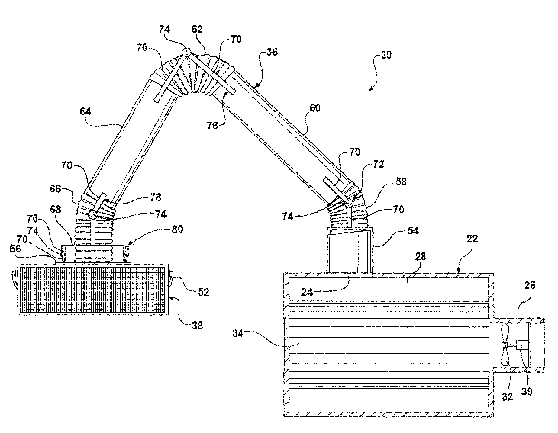
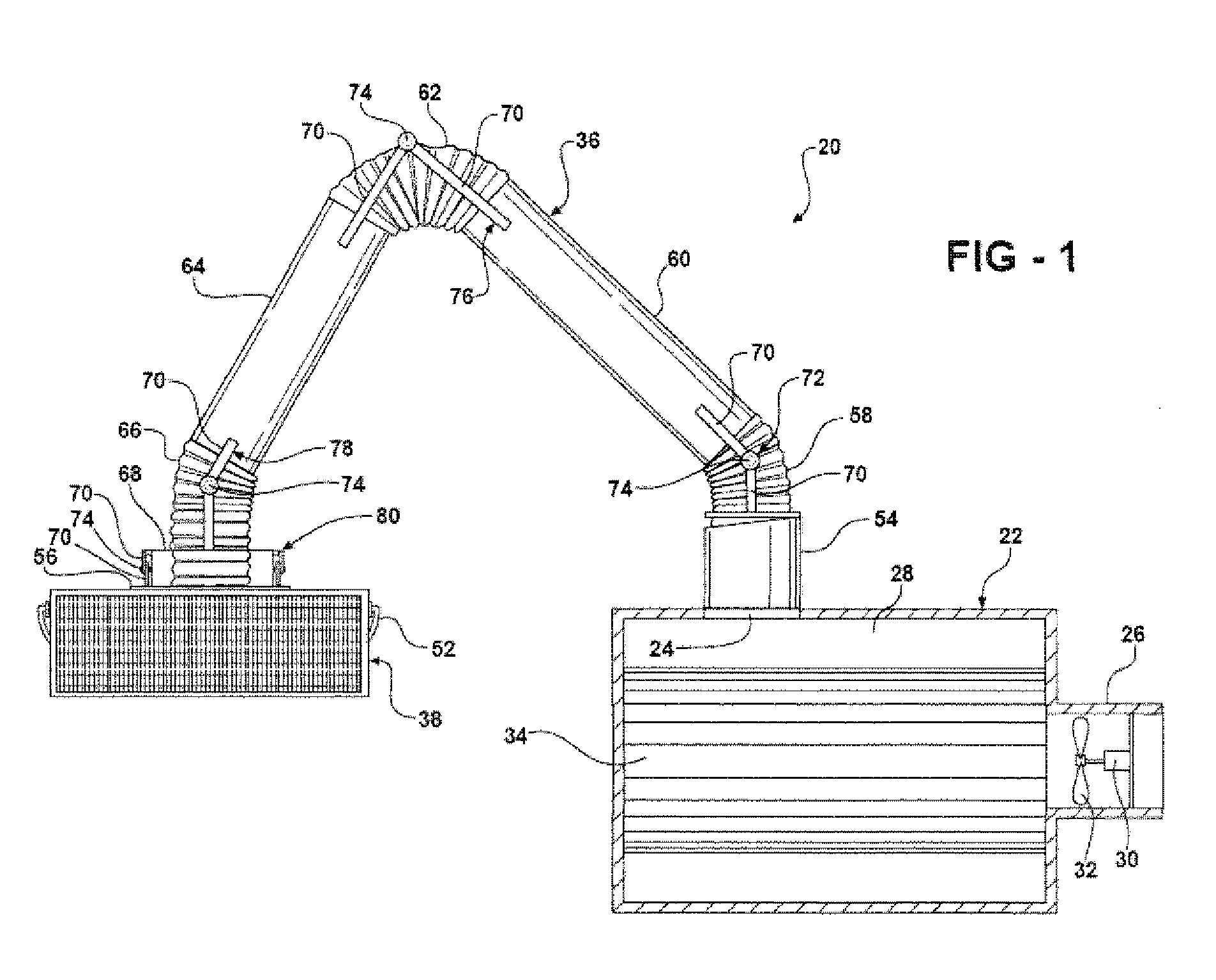
[0017]Referring to the Figures, wherein like numerals indicate corresponding parts throughout the several views, a positionable back draft assembly 20 is generally shown in FIG. 1.

[0018]The assembly 20 includes a filter housing 22, generally indicated, for filtering fumes and defining a housing inlet 24 for receiving the fumes and a housing outlet 26 for dispensing the fumes. An electric motor 30 is disposed in the filter housing 22. A fan 32 is operatively connected to the motor 30 for generating suction at the housing inlet 24 and for propelling the fumes out of the housing through the housing outlet 26. At least one filter 34 is disposed in the channel 28 for removing particulates from the fumes. One example of the filter housing 22 is the Robovent®, which is manufactured by Great Lakes Air Systems.

[0019]The assembly 20 further includes a duct arm 36, generally indicated, having a first end in fluid communication with the housing inlet 24 of the filter housing 22 and extending ou...


PUM

PropertyMeasurementUnit
Lengthaaaaaaaaaa
Lengthaaaaaaaaaa
Lengthaaaaaaaaaa

Abstract

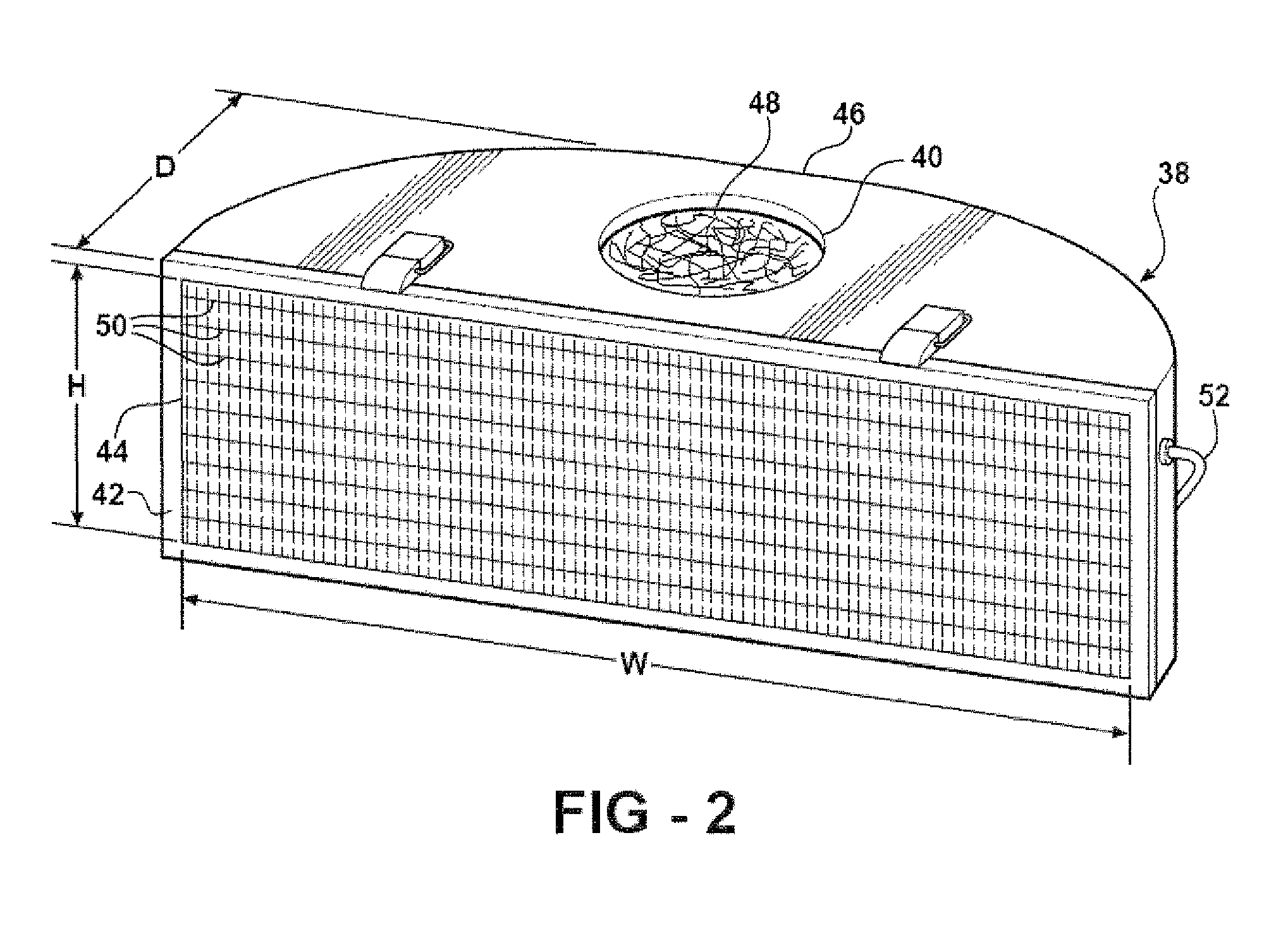
A filter housing, a duct arm and a hood which is positioned near the fume source as the duct arm extends between the hood and the filter housing for conveying the fumes from the hood to the filter housing. The filter housing includes a motor for generating suction at the hood inlet and for propelling the fumes out of the filter housing through a housing outlet. The motor has a power ranging from 7.5 to 10.0 horsepower for moving air through the assembly at speeds exceeding 6000 feet per minute (fpm) and at flow rates exceeding 2100 cubic feet per minute (cfm). The hood has a depth of 12 inches and the hood inlet has a width of 36.44 inches and a height of 12.51 inches.

Description

BACKGROUND OF THE INVENTION[0001]This invention claims priority to U.S. Provisional Application Ser. No. 60 / 942,870, filed Jun. 8, 2007.[0002]1. Field of the Invention[0003]The invention relates to air filtration systems and more particularly to positionable back draft assemblies that are used in industrial environments to filter and re-circulate the fumes from a fume source.[0004]2. Description of the Prior Art[0005]Many factories use machines or equipment, in welding for example, which create unhealthy fumes that must be filtered. Back draft assemblies, and positionable fume arms have been used near the source of the fumes, e.g. the work-piece being welded.[0006]Positionable fume arms often include a small hood and a fume arm. The hood is positioned near the fume source and the fume arm transfers the fumes to the filter housing where they are filtered. A low horsepower motor is used to drive a fan in these positionable arm systems.[0007]One example of a fume arm and a hood is disc...

Claims


Application Information

Patent Timeline
IPC IPC(8): B08B15/02A62C3/00B01D45/00
CPCB01D45/08B01D46/0002B01D50/002B08B15/02B01D50/20
Inventor REID, JAMES K.REID, JOHN
Owner ROBOVENT PROD GRP
Learn More