
Hybrid band directed energy target disruption

Active Publication Date: 2008-12-11
LOCKHEED MARTIN CORP
View PDF26 Cites 1 Cited by
  • Summary
  • Abstract
  • Description
  • Claims
  • Application Information

AI Technical Summary

Benefits of technology

[0007]The invention includes, in its various embodiments and aspects, a method and apparatus implementing a techniques for disrupting the operation of a target containing nonlinear electronic devices. The technique gen

Problems solved by technology

Target disruption temporarily interferes with the normal operation of the target.
Substantial experience has demonstrated that signals of frequencies at or above about 10 GHz yield unsatisfactory results.
However, low frequency signals still have some drawbacks.
For example, they require electrically large antennas to generate effective electric fields at relatively long ranges; this limitation disqualifies these sources from many applications.

Method used


Image

  • Hybrid band directed energy target disruption
  • Hybrid band directed energy target disruption
  • Hybrid band directed energy target disruption

Examples


Embodiment Construction

[0016]Illustrative embodiments of the invention are described below. In the interest of clarity, not all features of an actual implementation are described in this specification. It will of course be appreciated that in the development of any such actual embodiment, numerous implementation-specific decisions must be made to achieve the developers' specific goals, such as compliance with system-related and business-related constraints, which will vary from one implementation to another. Moreover, it will be appreciated that such a development effort, even if complex and time-consuming, would be a routine undertaking for those of ordinary skill in the art having the benefit of this disclosure.

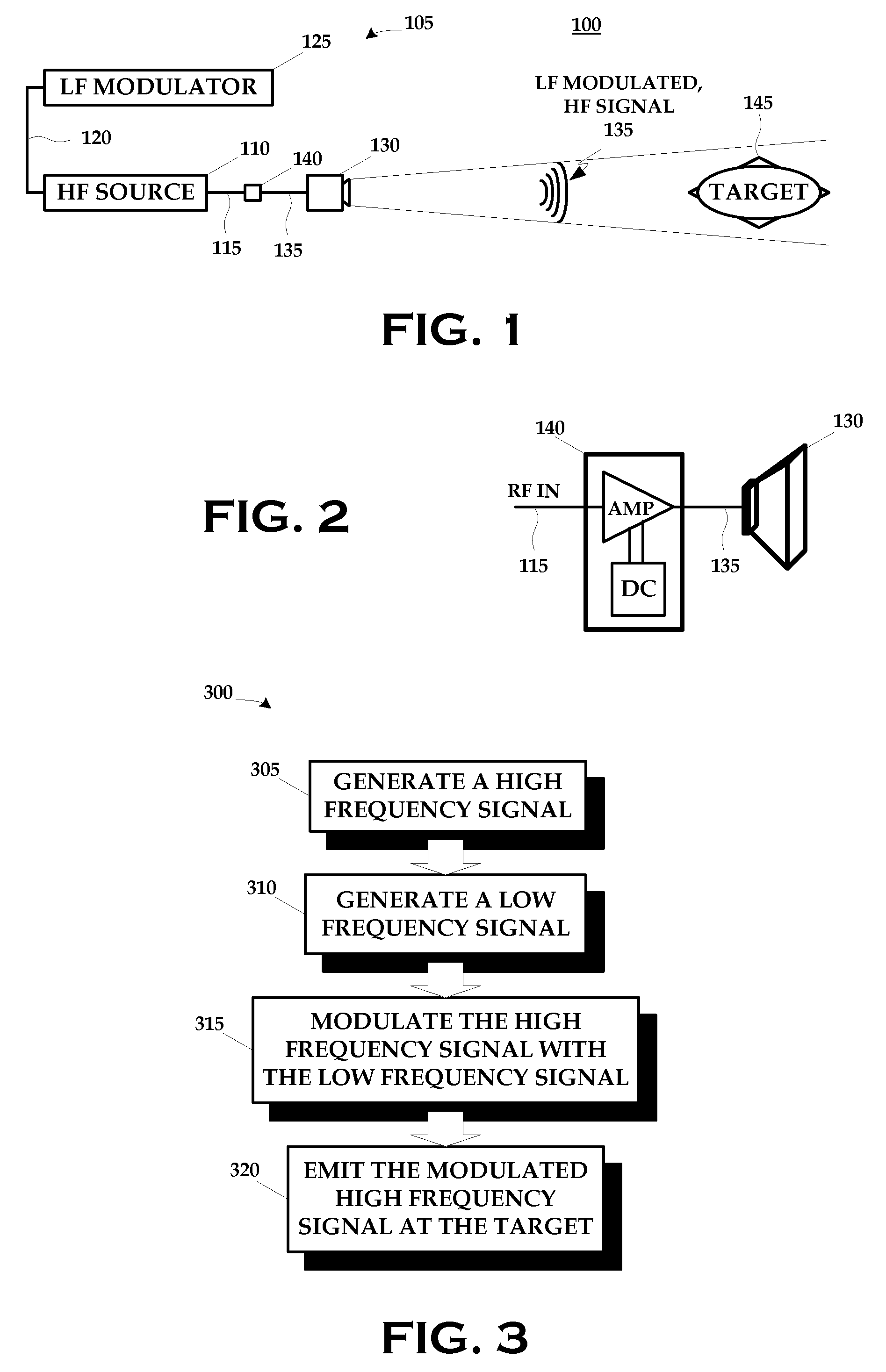
[0017]FIG. 1 is a block diagram of a scenario 100 in which an apparatus 105 is constructed and operated in accordance with the present invention. The apparatus 105 includes a high frequency (“HF”) source 110 whose output 115 is modulated by a signal 120 output by a low frequency (“LF”) modulator ...


PUM


Abstract

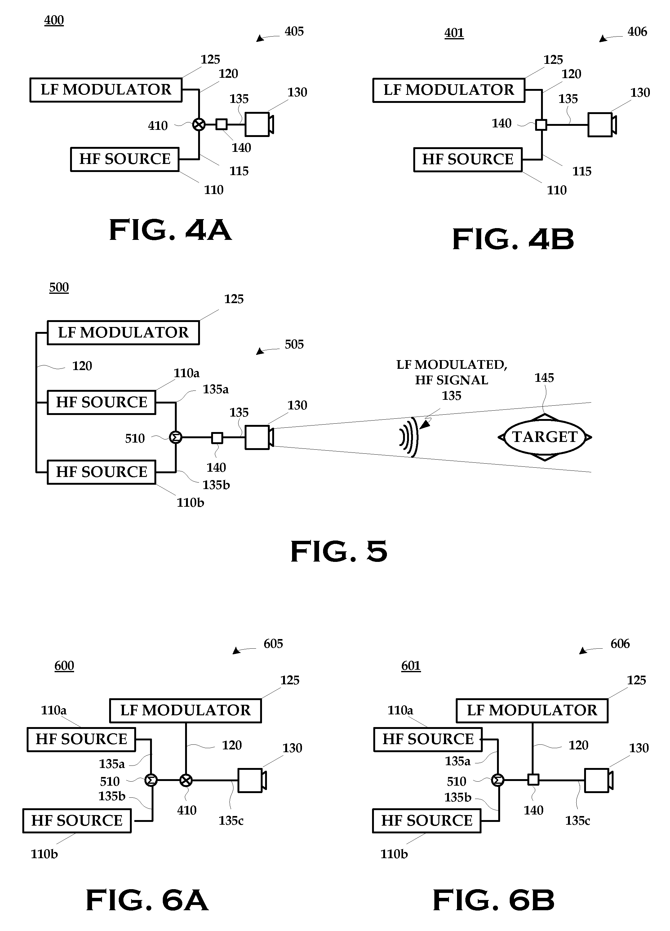
A technique for disrupting the operation of a target containing nonlinear electronic devices generally includes generating a high frequency signal; generating a low frequency signal; modulating the high frequency signal with the low frequency signal; and emitting the modulated high frequency signal at the target.

Description

BACKGROUND OF THE INVENTION[0001]1. Field of the Invention[0002]The present invention pertains to directed energy systems and, more particularly, to directed energy target disruption.[0003]2. Description of the Related Art[0004]One interesting application of directed energy systems is target disruption. Target disruption temporarily interferes with the normal operation of the target. It is non-destructive, and non-lethal. When the target is illuminated with the directed energy, it ceases to work correctly, only to resume proper function when the illumination is removed.[0005]Historically, target disruption has been performed using low frequency signals. Substantial experience has demonstrated that signals of frequencies at or above about 10 GHz yield unsatisfactory results. Conventional practice typically utilizes signals whose frequencies are at or below about 2 GHz. Signals in the 1 kHz-1 GHz range have been demonstrated to be particularly effective against certain target sets. Ho...

Claims


Application Information

Patent Timeline
IPC IPC(8): H04B1/00
CPCF41H13/0075H04B1/04H04B15/00
Inventor CALICO, STEVE E.HIDINGER, DAVID S.SCOTT, MICHAEL C.
Owner LOCKHEED MARTIN CORP
Learn More