
Electrophotographic photoreceptor, image forming apparatus, and process cartridge

Inactive Publication Date: 2008-12-04
RICOH KK
View PDF6 Cites 7 Cited by
  • Summary
  • Abstract
  • Description
  • Claims
  • Application Information

AI Technical Summary

Benefits of technology

[0023]Accordingly, an object of the present invention is to provide an electrophotographic photoreceptor which has high sensitivity and durability and capable of producing high quality images for a long period of time.
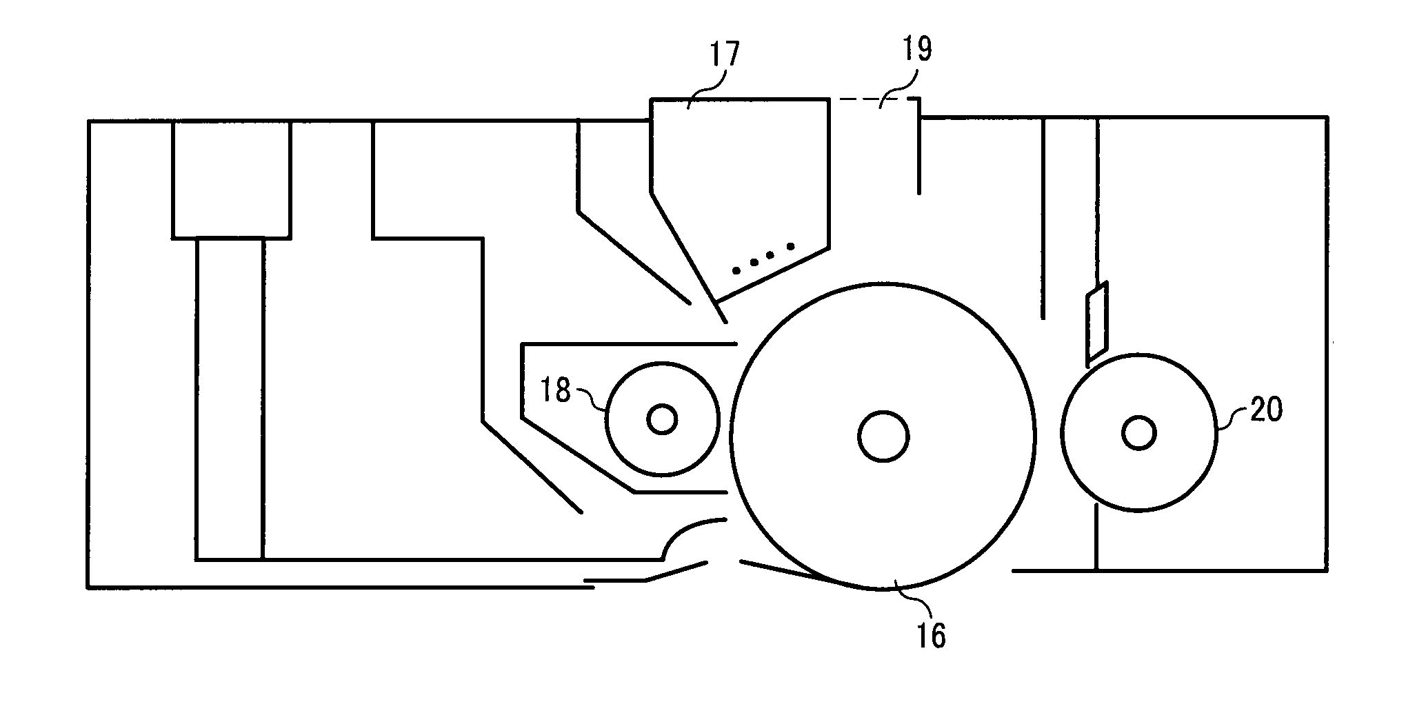
[0025]Yet another object of the present invention is to provide a process cartridge which realizes easy replacement of the electrophotographic photoreceptor.

Problems solved by technology

Photoreceptors using organic photoconductive materials (hereinafter “organic photoreceptors” or “photoreceptors”, unless otherwise described) are widely used for laser printers and digital copiers using electrophotography, due to their cost, manufacturability, and non-polluting properties.
However, the photosensitive layers of the organic photoreceptors are easily abraded by repeated use, and therefore the potential and photosensitivity of the photoreceptor tend to deteriorate.
Further, a scratch made on the surface of the photoreceptor tends to cause background fouling and deterioration of density and quality of the resultant images.
However, another problem occurs when these methods are used to prevent the abrasion of the photoreceptor.
Specifically, oxidized gases, such as ozone and NOx arising due to use conditions or environment, adhere to the surface of the photosensitive layer and decrease the surface resistance thereof, resulting in a problem such as blurring of the resultant images.
In order to decrease the influence of substances causing the blurred images, there is a method of equipping the photoreceptor with a heater, which is a large drawback for downsizing the apparatus and decreasing the electric power consumption.
However, the additive typically does not have photoconductivity, and therefore including much amount thereof in the photosensitive layer causes problems such as deterioration of sensitivity and increase of residual potential of the resultant photoreceptor.
However, such photoreceptors inevitably produce blurred and low-resolution images, and it is difficult to achieve both high durability and high quality of the resultant images.
The problem lies in a contradictory fact that high surface resistance of the photosensitive layer is preferable to prevent the blurred images and low surface resistance thereof is preferable to prevent the increase of residual potential.
However, as is generally known, negative corona discharge is unstable compared to positive corona discharge.
Therefore, scorotron discharge, which is costly, is preferably employed, resulting in increasing cost.
Negative corona discharge produces a large amount of ozone, which is a substance causing chemical damage.
Consequently, the resultant images have low image quality.
In order to prevent the ozone from discharging out of the apparatus, most copiers and printers employing a negative charging method are equipped with an ozone filter, resulting in cost rise.
Furthermore, the large amount of ozone thus produced causes environmental pollution.
Such photoreceptors have a drawback that properties thereof largely vary due to environmental gases such as exhausts from kerosene fan heaters or cars.
The photoreceptor includes a diphenoquinone derivative as an electron transport material, but the diphenoquinone derivative has relatively low charge transportability.
Therefore, photoconductive properties of the photoreceptor are not satisfactory enough in consideration of increasing printing speed and downsizing of copiers and printers.
In addition, the photoreceptor may cause blurred images by repeated use.
However, the aromatic compound has low charge transportability, and therefore the photoreceptor may not respond to the demands for high-sensitivity and high-speed printing.
The added amount of the aromatic compound may be also limited.
If such a stilbene compound is solely included in a photosensitive layer as a hole transport material, the photosensitive layer may potentially have poor charge retention ability or the charge retention ability may gradually deteriorate by repeated use.
Therefore, a fatal problem lies in the fact that the stilbene compounds are difficult to be put into practical use.
Consequently, the resultant photoreceptor may have extremely low sensitivity and large residual potential.
However, high-speed printing and downsizing of the apparatus along with reducing the diameter of the photoreceptor have not realized with the photoreceptor.

Method used


Image

  • Electrophotographic photoreceptor, image forming apparatus, and process cartridge
  • Electrophotographic photoreceptor, image forming apparatus, and process cartridge
  • Electrophotographic photoreceptor, image forming apparatus, and process cartridge

Examples


manufacturing example 1

Preparation of Compound No. 20

[0158]A mixture of 2.68 g (10.0 mmol) of naphthalene-1,4,5,8-tetracarboxylic acid dianhydride (from Tokyo Chemical Industry Co., Ltd.), 30 ml of N,N′-dimethylformamide, and 3.68 g (20.0 mmol) of 1,1-diphenylhydrazine (from Tokyo Chemical Industry Co., Ltd.) was agitated for 2 hours at 60° C. under an argon gas stream, and 100 ml of water were added thereto. The precipitated crystals were collected by filtration, and dried in a reduced-pressure heating drier. Thus, 3.43 g (i.e., the yield was 57.1%) of brown crude crystals were prepared. The brown crude crystals was then treated with a silica gel column, using a mixed solvent of toluene and ethyl acetate in a volume ratio of 20 / 1 as eluant, recrystallized with toluene, and dried in a reduced-pressure heating drier. Thus, 7.02 g (i.e., the yield was 29.7%) of orange-red crystals of the compound No. 20 having the following formula were prepared:

[0159]The result of ultimate analysis is shown in Table 1.

TABL...

manufacturing examples 2 to 5

Preparation of Compounds Nos. 1, 10, 15, and 37

[0162]The procedure for preparation of the compound No. 20 in Manufacturing Example 1 was repeated except that the hydrazine compound (i.e., 1,1-diphenylhydrazine) was replaced with other compounds. Thus, the compounds Nos. 1, 10, 15, and 37 were prepared.

[0163]The measurement results of these compounds are shown in Table 2. The infrared absorption spectrums, measured by a KBr pellet method, are shown in FIGS. 11 to 14.

TABLE 2Manu-Ultimate Analysis (%)facturingCom-DecompositionMeasured ValueExamplepoundYieldPoint(Calculated Value)No.No.(%)(° C.)CHN2137.432861.284.5215.84(61.36)(4.58)(15.90)31061.335276.904.908.78(76.81)(4.91)(8.53)41556.538070.684.1011.98(70.58)(4.23)(11.76)53746.536276.224.369.02(76.42)(4.49)(8.91)

manufacturing example 6

Preparation of Compound No. 38

[0164]A mixture of 2.68 g (10.0 mmol) of naphthalene-1,4,5,8-tetracarboxylic acid dianhydride (from Tokyo Chemical Industry Co., Ltd.) and 25 ml of N,N′-dimethylformamide was agitated at 80° C. under an argon gas stream. A solution including 0.61 g (10 mmol) of 1-methyl-1-phenylhydrazine (from Tokyo Chemical Industry Co., Ltd.) and 10 ml of N,N′-dimethylformamide was dropped therein over a period of 2 hours. The mixture was further agitated for 30 minutes at 80° C., and subsequently a solution including 0.99 g (10 mmol) of 1-benzyl-1-phenylhydrazine (from Tokyo Chemical Industry Co., Ltd.) and 5 ml of N,N′-dimethylformamide was added thereto. The mixture was further agitated for 2 hours at 80° C. The mixture was poured into 100 ml of water, and the precipitated crystals were collected by filtration, and dried in a reduced-pressure heating drier. Thus, brown crude crystals were prepared. The brown crude crystals were then treated with a silica gel column...


PUM


Abstract

An electrophotographic photoreceptor including a conductive substrate and a photosensitive layer located overlying the conductive substrate which includes a naphthalenetetracarboxylic acid diimide derivative having a specific formula; and an image forming apparatus and a process cartridge using the electrophotographic photoreceptor are provided.

Description

BACKGROUND OF THE INVENTION[0001]1. Field of the Invention[0002]The present invention relates to an electrophotographic photoreceptor. In addition, the present invention relates to an image forming apparatus and a process cartridge using the electrophotographic photoreceptor.[0003]2. Discussion of the Background[0004]Information processing systems using electrophotography are making remarkable progress recently. Particularly, laser printers and digital copiers, in which information is converted into digital signals and recorded by means of light, have been extremely improved in terms of printing quality and reliability. Further, technologies used in these laser printers and digital copiers are applied to laser printers and digital copiers capable of printing full-color images by merging with high-speed printing technologies. For the above reasons, photoreceptors used for such laser printers and digital copiers are required both to produce high quality images and to have high durabil...

Claims


Application Information

Patent Timeline
IPC IPC(8): G03G15/04G03G15/00G03G15/02
CPCG03G5/0616G03G5/0651G03G5/0668
Inventor SHIMADA, TOMOYUKI
Owner RICOH KK
Learn More