
Nano-imprinting process

a technology of nano-imprinting and printing process, which is applied in the direction of manufacturing tools, coatings, and catheter, etc., can solve the problems of high cost of molding, inaccurate definition of feature patterns, and high cost of special inks, so as to reduce the degradation of accuracy caused by multiple processes, reduce the cost of molding, and simplify the complicated steps

Inactive Publication Date: 2008-12-04
NAT CHENG KUNG UNIV
View PDF7 Cites 3 Cited by
  • Summary
  • Abstract
  • Description
  • Claims
  • Application Information

AI Technical Summary

Benefits of technology

[0011]One aspect of the present invention is to provide a nano-imprinting process, which can simplify the complicated steps required in typical nano-imprinting processes, so that the degradation of the accuracy caused by multiple processes can be reduced to rapidly and accurately define feature patterns to an imprinting material layer on a surface of a substrate desired to be imprinted, and to greatly reduce the contamination resulted from the processes.
[0012]Another aspect of the present invention is to provide a nano-imprinting process, in which the formation of an etching / exposure mask required in the definition of feature patterns on an imprinting material layer and a subsequent dry etching or exposure process can be completed by directly embedding the exposure / etching mask into the imprinting material layer, so that the time and the fabrication cost of the nano-imprinting process can be greatly reduced, to achieve low-cost, rapid and large-area imprinting. Therefore, the nano-imprinting process has great ability of mass production.
[0013]Still another aspect of the present invention is to provide a nano-imprinting process, which does not need an external heating source with high temperature during the imprinting process, so that the consumption of the energy can be saved to greatly reduce the production cost and to achieve an environment-friendly nano-imprinting process with low energy consumption.
[0014]Yet another aspect of the present invention is to provide a nano-imprinting process, which does not need an applied heating source with high temperature, so that electronic devices preset on a substrate will not be damaged by heat to enhance the process yield and the product reliability.

Problems solved by technology

However, during the high temperature heating treatment of the imprinting material layer, a substrate is in a high temperature circumstance, so that circuit layout structures pre-formed in the substrate are damaged, and an ill effect of stress remaining on the surface of the substrate is caused by a large temperature difference.
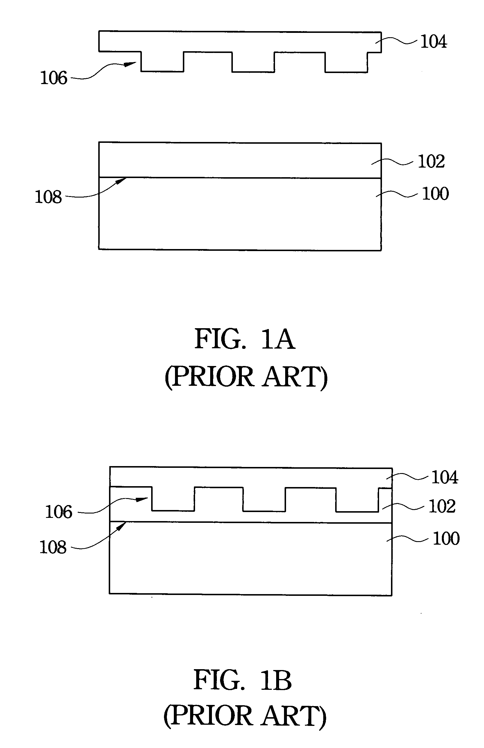
However, the manufacturing processes of the quartz mold and the PDMS mold both are very complicated, and the quartz mold and the PDMS mold are difficult to be manufactured, so that the molds are expensive.
However, the special ink is very expensive, and the ink spreads when a feature pattern is defined to an imprinting material layer to cause a defect of the inaccurate definition of the feature pattern.
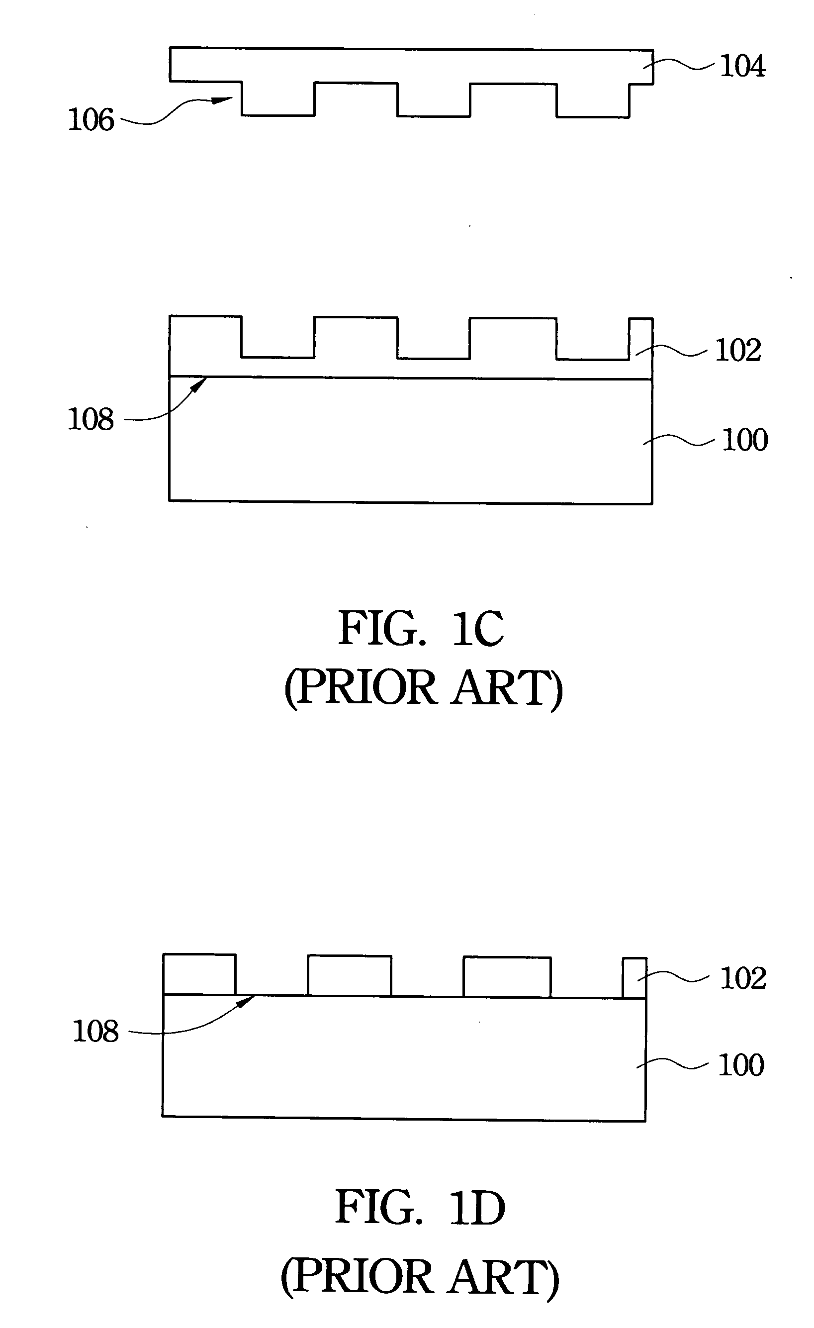
However, the step of setting the mask layer 110 is very complicated, and the procedures of firstly etching the imprinting material layer 102 and then setting the mask layer 110 increase the complexity of the process.

Method used


Image

  • Nano-imprinting process
  • Nano-imprinting process
  • Nano-imprinting process

Examples


Embodiment Construction

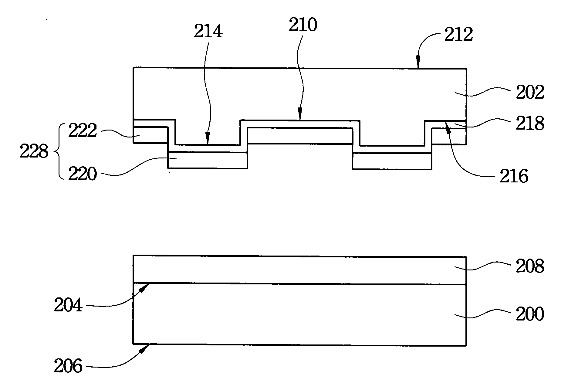
[0020]The present invention discloses a nano-imprinting process, which can directly embed an etching mask into an imprinting material layer, so that the process can be effectively simplified to rapidly and accurately complete the nano-imprinting process. In order to make the illustration of the present invention more explicit, the following description is stated with reference to FIGS. 2A through 2F.

[0021]FIGS. 2A through 2F are schematic flow diagrams showing a nano-imprinting process in accordance with a preferred embodiment of the present invention. In an exemplary embodiment, a substrate 200 is provided, wherein the substrate 200 includes a surface 204 and a surface 206 on opposite sides. The material of the substrate 200 is, for example, a semiconductor material, a plastic material, a piezoelectric material, a dielectric material, a glass material, a ceramic material, an electrically conductive material, metal or any combinations of the aforementioned materials. In an embodimen...


PUM

PropertyMeasurementUnit
wavelengthaaaaaaaaaa
temperatureaaaaaaaaaa
piezoelectricaaaaaaaaaa

Abstract

A nano-imprinting process is described, comprising: providing a substrate including an imprinting material layer covering a surface of the substrate; providing a mold including protruding features set on a surface of the mold covered with an anti-adhesion layer; forming a transferring material layer on a top surface of each protruding feature; embedding the transferring material layer into a first portion of the imprinting material layer; removing the mold and separating the mold and the transferring material layer simultaneously to transfer the transferring material layer into the first portion of the imprinting material layer and to expose a second portion of the imprinting material layer; using the transferring material layer as a mask to remove the second portion of the imprinting material layer and a portion of the substrate; and removing the first portion of the imprinting material layer and the transferring material layer.

Description

RELATED APPLICATIONS[0001]This application claims priority to Taiwan Application Serial Number 96119831, filed Jun. 1, 2007, which is herein incorporated by reference.FIELD OF THE INVENTION [0002]The present invention relates to a macro / nano-imprinting process, and more particularly, to a mask-embedded imprinting process.BACKGROUND OF THE INVENTION [0003]In typical imprinting techniques, such as a hot embossed or laser assisted nano-imprinting, an external high energy heating source is needed to heat imprinting material layers to melt the imprinting material layers. However, during the high temperature heating treatment of the imprinting material layer, a substrate is in a high temperature circumstance, so that circuit layout structures pre-formed in the substrate are damaged, and an ill effect of stress remaining on the surface of the substrate is caused by a large temperature difference.[0004]In addition, an imprinting material adopted in an ultraviolet (UV) curing nano-imprinting...

Claims


Application Information

Patent Timeline
Patent Type & Authority Applications(United States)
IPC IPC(8): B29C41/22
CPCB29C59/022B29C2059/023Y10S977/887
Inventor LEE, YUNG-CHUNHSIAO, FEI-BINCHIU, CHENG-YU
Owner NAT CHENG KUNG UNIV
Learn More