
Suspension rod tensioning arrangements for supporting cryogenic equipment within a cryostat

a technology of suspension rods and tensioning nut ends, which is applied in the direction of rod connections, domestic cooling apparatus, container discharge methods, etc., can solve the problems of difficult use, high manufacturing cost, and inability to meet the needs of cryogenic equipment, so as to prevent loosening of the tensioning nut, reduce the bending load of the rods, and maximize the thermal length

Active Publication Date: 2008-12-04
SIEMENS HEALTHCARE LTD
View PDF11 Cites 7 Cited by
  • Summary
  • Abstract
  • Description
  • Claims
  • Application Information

AI Technical Summary

Benefits of technology

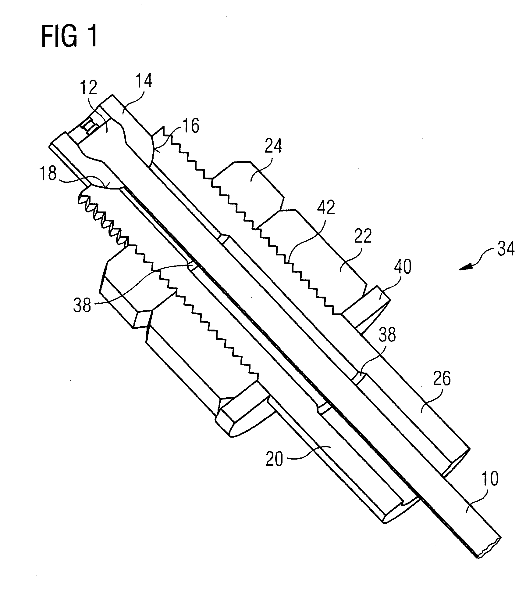
"The present invention provides a cryostat with a compact and low-heat load design for supporting cryogenically cooled equipment. The invention achieves this by increasing the thermal length of the suspension rods and simplifying the operation of applying preload tension to the support rod. The invention also allows for angular misalignment and optimizes fatigue life by avoiding deformation or thinning of the rod. The cryostat includes an outer vacuum vessel containing cryogenic equipment suspended from the outer vacuum vessel by a number of suspension rods, at least one of which is provided with a tensioning and retaining mechanism that holds the suspension rod in tension. The tensioning and retaining mechanism includes a tubular rod carrier that passes through a hole or slot in the suspension bracket and has an axial bore through which the rod passes, a thread on the outer surface of the rod carrier along at least a part of its length, and a rod bearing surface for transmitting force to the rod. A tensioning nut is threaded onto the thread that braces against the suspension bracket to apply tension to the rod."

Problems solved by technology

In addition, to minimize thermal load, the diameter of the non-threaded part of the rods should be reduced below the diameter required for thread forming, which is costly in manufacture.
Features such as flats may be provided on the rod to prevent rotation during tensioning of the nut; these are expensive to manufacture and difficult to use, for example several spanners may be required simultaneously in order to tension nuts on a suspension rod.

Method used


Image

  • Suspension rod tensioning arrangements for supporting cryogenic equipment within a cryostat
  • Suspension rod tensioning arrangements for supporting cryogenic equipment within a cryostat
  • Suspension rod tensioning arrangements for supporting cryogenic equipment within a cryostat

Examples


Embodiment Construction

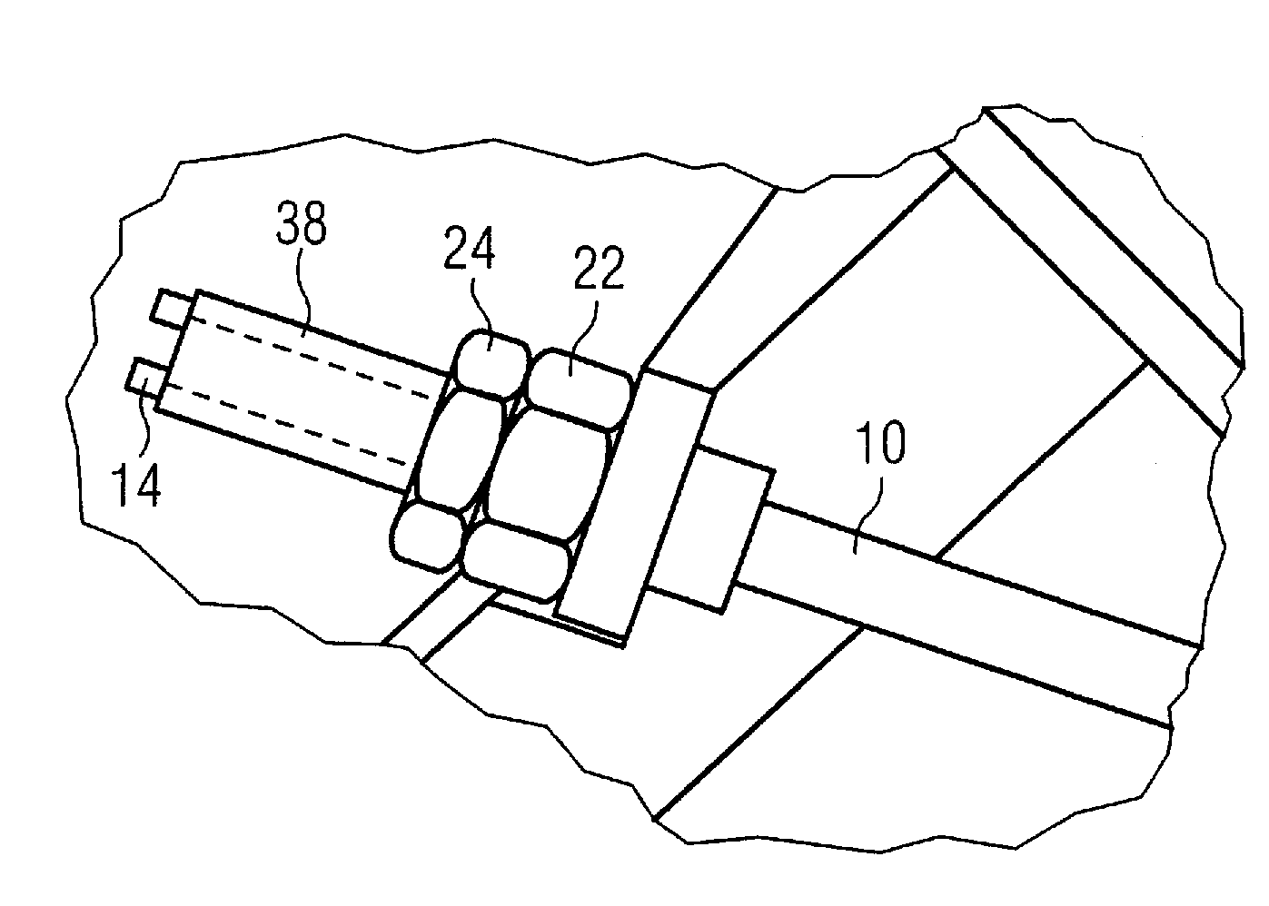
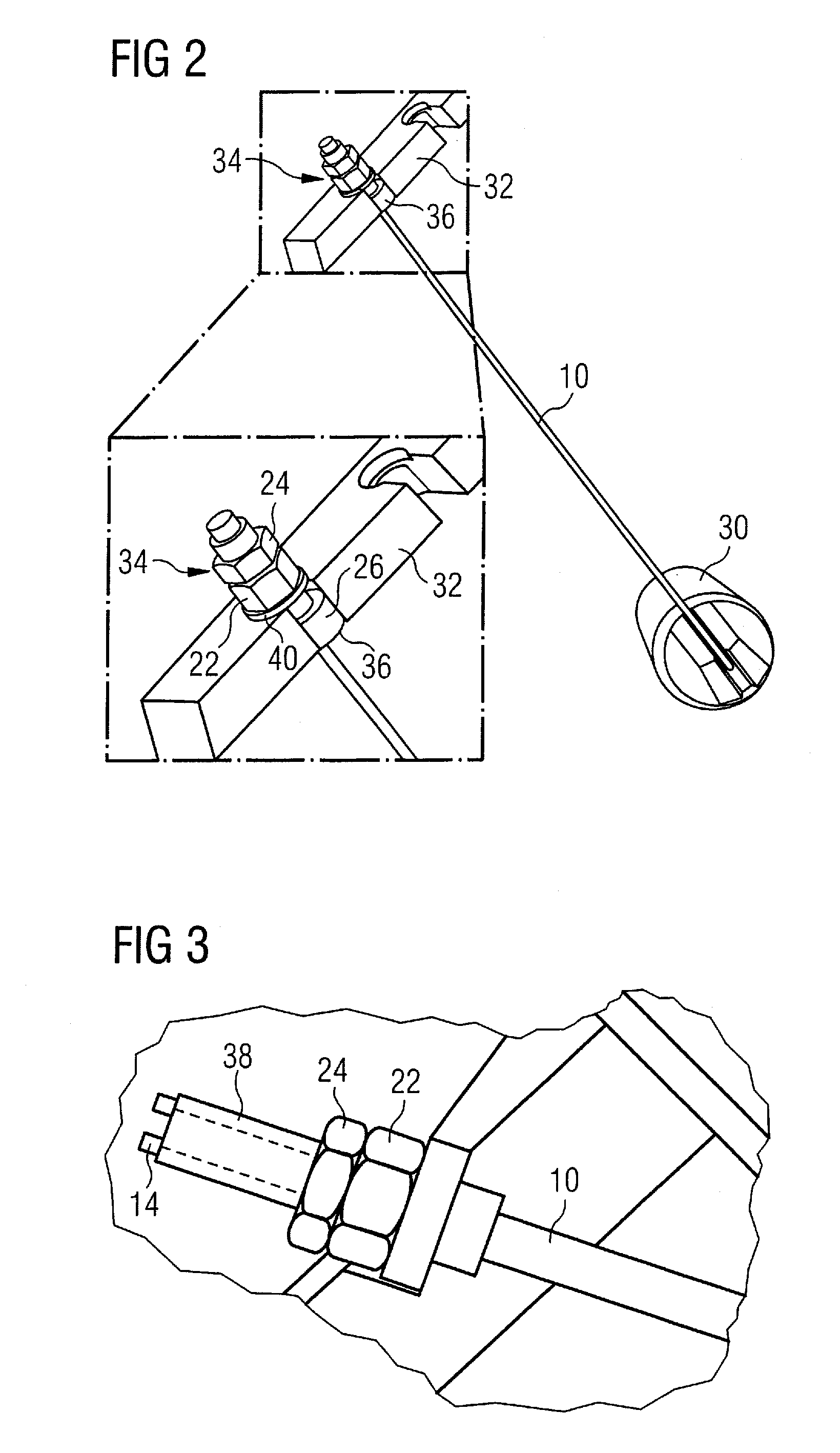
[0022]The tension rod support arrangement according to a feature of the present invention provides at least some of the following features: Structure is provided for achieving a consistent application of preload. Angular misalignment of the rod must be tolerated within a defined range. The capability exists to accommodate variations in the actual and required length of the rod. The thermal length of the rods is to be maximized between the supported article, such as a superconducting magnet, and a support surface. A locking arrangement is provided to prevent loosening of the suspension rod, and so to maintain an applied preload. The arrangement can be produced by an assembly process that allows the tensioning end of the rod to be fitted after location of the opposite end of the rod. The arrangement has an optimized fatigue life. Twisting of the suspension rod during length adjustment is prevented.

[0023]FIG. 2 shows an entire suspension unit according to an embodiment of the present i...


PUM


Abstract

A cryostat, comprising an outer vacuum vessel containing cryogenic equipment suspended from the outer vacuum vessel by a number of suspension rods. At least one of the suspension rods is provided with a tensioning and retaining mechanism for holding that suspension rod in tension braced against a suspension bracket). This tensioning and retaining mechanism includes a tubular rod carrier arranged, in use, to pass through a hole or slot in the suspension bracket, the rod carrier having an axial bore through which, in use, the rod may pass; a thread on its outer surface along at least part of its length; and a rod bearing surface for, in use, transmitting force to the rod. This tensioning and retaining mechanism also comprises a tensioning nut threaded onto the thread so as to, in use, brace against the suspension bracket to urge the tubular rod carrier in the direction of the rod bearing surface so as to apply tension to the rod.

Description

BACKGROUND OF THE INVENTION[0001]1. Field of the Invention[0002]The present invention concerns a suspension rod tensioning arrangement of the type used to support cryogenic equipment within a cryostat.[0003]2. Description of the Prior Art[0004]In order to improve access for clinicians and improve patient comfort, it is advantageous to make magnets used in MRI systems as compact as possible. The superconducting magnet typically used must be held at cryogenic temperatures, and this requires that superconducting magnets must be suspended by a suspension system, and heat conduction through the suspension system must be minimized.[0005]Magnetic resonance imaging (MRI) systems typically include a cryogenically cooled superconducting magnet, retained within a cryostat, essentially comprising an evacuated outer vacuum vessel. Suspension arrangements are typically provided, and comprise a number of support rods or bands or similar. The suspension arrangements are designed to have very high t...

Claims


Application Information

Patent Timeline
Patent Type & Authority Applications(United States)
IPC IPC(8): F25B19/00F16M13/00F16B7/18F25D19/00
CPCF16B31/04G01R33/3802G01R33/3806Y10T403/33Y10T403/68Y10T403/335G01R33/3815F16B17/006F16S3/06
Inventor MANN, NICHOLASRIDLEY, JENNIFER
Owner SIEMENS HEALTHCARE LTD
Learn More