
Method and Transmitter, Receiver and Transceiver Systems for Ultra Wideband Communication

a technology of transmitter and receiver, applied in the field of methods and transmitter, receiver and transceiver systems for ultra wideband communication, can solve the problems of limiting the possible data transmission rate of band-limited systems, degrading the system's performance, and most conventional radio systems are bandwidth limited, so as to improve the system capacity, reduce interference, and increase the data transmission rate

Inactive Publication Date: 2008-11-27
AGENCY FOR SCI TECH & RES
View PDF6 Cites 13 Cited by
  • Summary
  • Abstract
  • Description
  • Claims
  • Application Information

AI Technical Summary

Benefits of technology

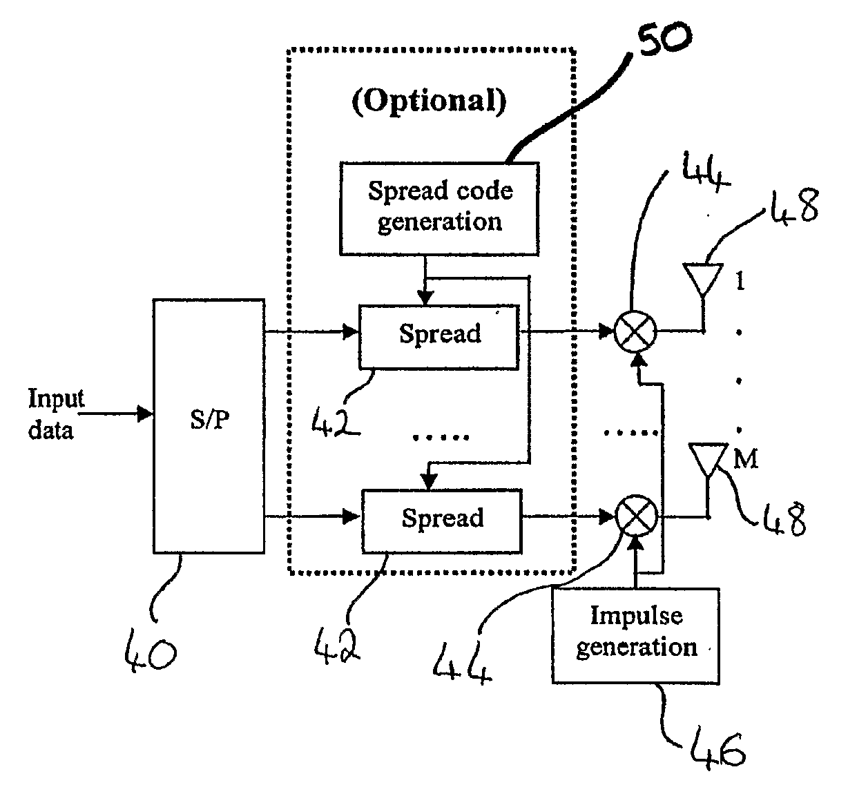
The present invention proposes a system and method for transmitting and receiving data as a pulsed ultrawide band signal using a single antenna and oversampling at the transmitter and a matched filter at the receiver. The system includes a converter for converting the signal to a parallel sequence, a modulator for converting the parallel sequence to a parallel stream of impulse trains with equal pulse repetition periods, a delay unit for delaying the impulse trains, a signal combining unit for combining the delayed pulse trains to form a combined signal, and an antenna for transmitting the combined signal. The method involves converting the signal to a parallel sequence, filtering it with a matched filter, processing it with a low-pass filter, and converting it to a digital signal. The technical effects of the invention include improved transmission diversity, reduced interference, and improved data transmission and reception using a single antenna.

Problems solved by technology

Most conventional radio systems are bandwidth limited, trading power to improve the data rate.
In accordance with Shannon's criteria for channel capacity, the transmission power required to achieve satisfactory performance in a radio system increases exponentially with data rate, thereby limiting the possible data transmission rate for band-limited systems.
In conventional communication systems, the arrival of reflected waves via different path lengths causes constructive and destructive interference at the receiver, degrading the system's performance.
However, in such systems, the propagation characteristics of high-rate UWB transmission show that the dispersion is too great and may cause interference with adjacent UWB pulses, but the short transmission pulses in such systems are relatively immune to multipath effects.
Designing a transceiver structure for such high-rate systems, with unlimited bandwidth is a challenging task.
Complex design issues relating to both radio frequency (RF) and baseband signal processing at the transmitter and the receiver must be considered.
However, this kind of repeat transmission scheme is highly impractical for many systems, due to the potentially high data rates.
Moreover, high rate communication systems have a significantly higher number of paths and so may not give much improvement in system performance, considering system capacity and resource allocation.
The extra cost in space diversity is the additional RF circuitry and associated complexity for each antenna.
The diversity combining methods discussed above are severely limited for systems with comparatively low data rates.
Due to resource limitations, the receiver hardware cannot process all multipath components satisfactorily.
This limitation will increase the multipath interference and considerably affect the system capacity.
As mentioned above, using re-transmissions to obtain time and frequency diversities are highly impractical for high rate systems due to the limited available resources.
Moreover, these systems are highly inefficient in terms of bandwidth efficiency.
However, it requires multiple antennae at the receiver and transmitter and is more suitable for base stations due to the size and complexity constraints of mobile stations.
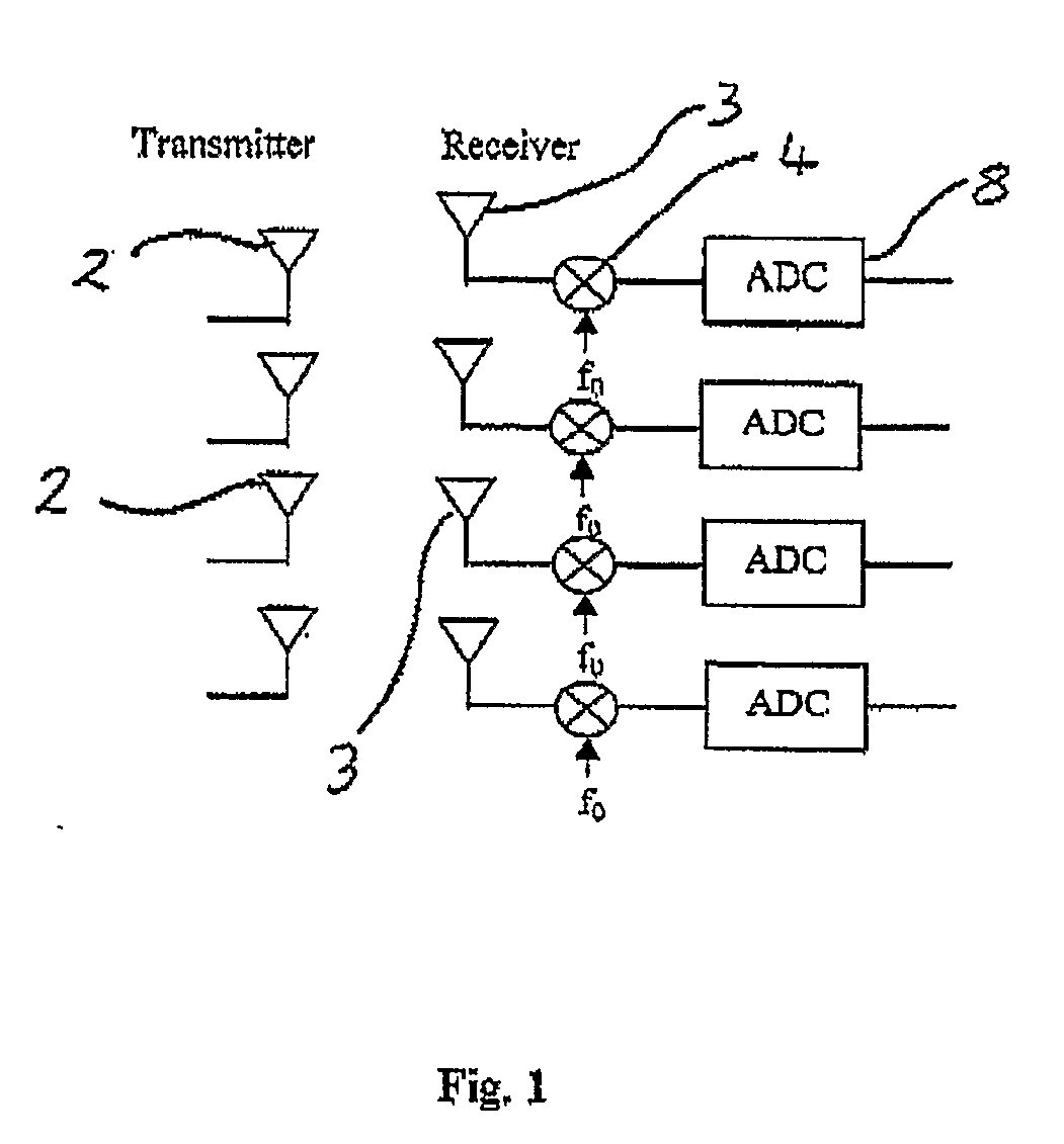
If multiple antennae are used at the receiver, multiple receiver filters will be required, as well as local oscillators (LO) and ADCs, thereby increasing the cost, size and complexity of the receivers.
Furthermore, the problems with multipath interference at high data rate and multi-stream interference across antennae are the major issues for systems with space diversity.
Incorporating space diversity in the transceiver structure can increase the data rate further, but the above limitations for space diversity are applicable for UWB systems as well.
These limitations are more significant for UWB systems, mainly because of the cost, complexity and size constraints of WPAN devices.

Method used


Image

  • Method and Transmitter, Receiver and Transceiver Systems for Ultra Wideband Communication
  • Method and Transmitter, Receiver and Transceiver Systems for Ultra Wideband Communication
  • Method and Transmitter, Receiver and Transceiver Systems for Ultra Wideband Communication

Examples


Embodiment Construction

[0089]The present invention will be described in connection with FIGS. 2a to 15(b).

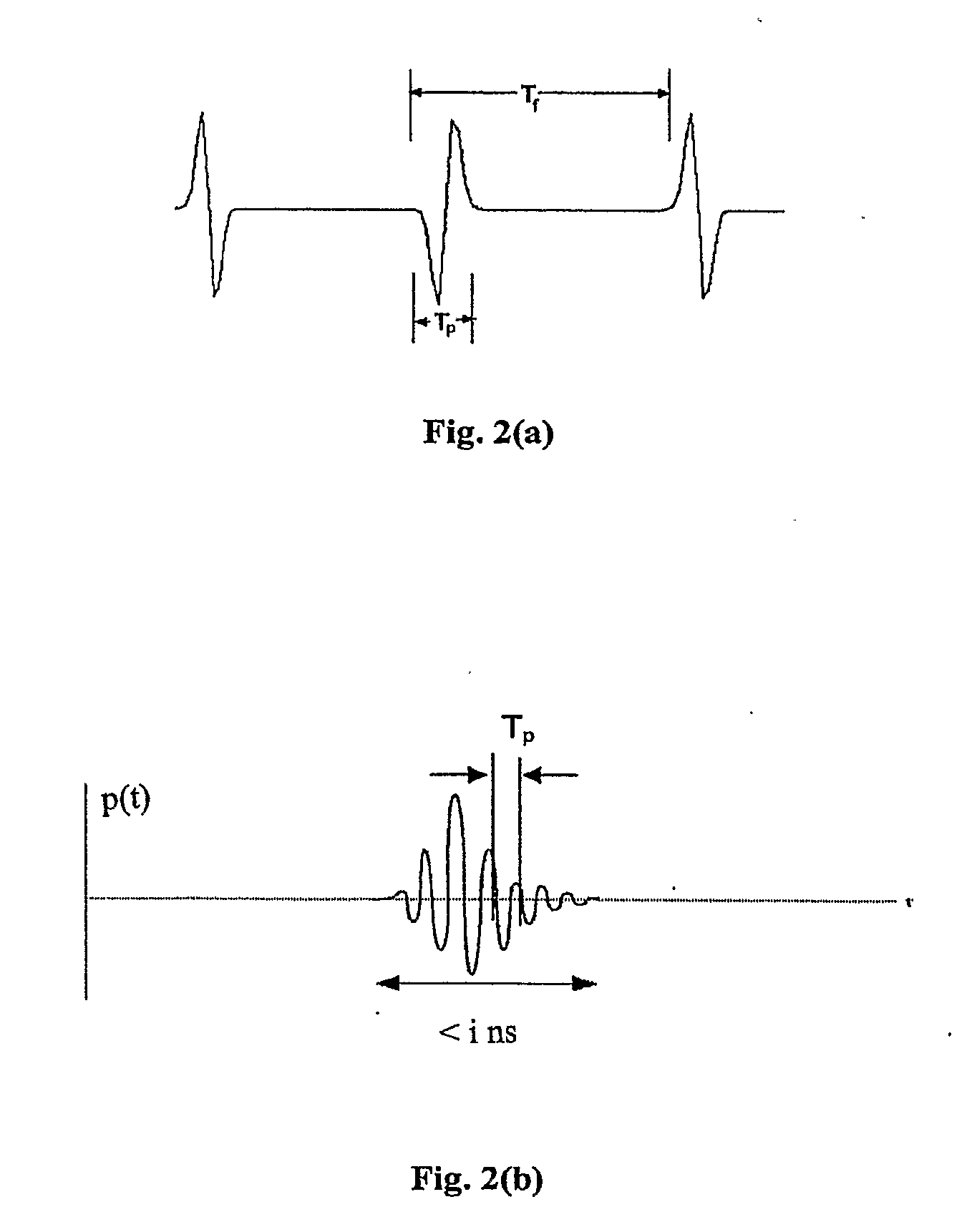
[0090]A preferred embodiment of the present invention uses ultra wideband (UWB) pulses for transmitting information. In general, UWB systems transmit sequences of information carried on very narrow width (Tp) pulses that are spaced at regular intervals depending on the modulation. These pulses can be formed using a single basic pulse shape generator and are very short in duration, typically much shorter than the interval corresponding to a single bit or chip. The interval between two adjacent pulses is called the pulse repetition period (Tf).

[0091]FIG. 2(a) shows an example waveform of a pulse sequence generated by a UWB transmitter, for example, in an embodiment according to the present invention. A stream of pulses is shown, each pulse comprising a positive and negative excursion. The order in which the said excursions occur indicates the level of the data pulse being passed through the transceiver....


PUM


Abstract

A transmitter for transmitting data as a pulsed ultrawide band signal comprises a serial-to-parallel converter (54) for converting the signal to be transmitted to a parallel sequence, a modulator (64) to convert the parallel sequence to a parallel stream of impulse trains. A delay unit (60) delays the parallel streams of impulse trains by different time intervals within the same pulse repetition period. The delayed pulse streams are combined so that the pulses in the streams occur within the pulse repetition period of a single pulse. An antenna (52) is used to transmit the combined signal. A receiver comprises an antenna (72) for receiving a transmitted pulsed ultrawide band signal having two or more interleaved pulse trains with equal pulse repetition periods, the pulse repetition period being greater than the pulse spacing in the interleaved signal. A matched filter filters the received signal, the filter being matched to the pulse shape of the received signal. A low-pass filter (74) is coupled to the matched filter and an analogue-to-digital converter (76) is coupled thereto. A serial-to-parallel conversion unit (78) is coupled to the converter (76) to sample the digital signal at a rate greater than the pulse repetition frequency of the received signal. A signal processor (80) is coupled to the serial-to-parallel conversion unit (78) to produce an output signal representative of the received data.

Description

FIELD OF INVENTION[0001]The present invention relates to a method and transmitter, receiver and transceiver systems for ultra wideband communication, such as an ultra wideband radio system.BACKGROUND[0002]Most conventional radio systems are bandwidth limited, trading power to improve the data rate. In accordance with Shannon's criteria for channel capacity, the transmission power required to achieve satisfactory performance in a radio system increases exponentially with data rate, thereby limiting the possible data transmission rate for band-limited systems. To overcome this problem, ultra-wideband (UWB) systems have been proposed in which the channel capacity scales almost linearly with bandwidth. UWB communication systems are based on the generation and transmission of very short pulses, in the range of a few tens of picoseconds or a few nanoseconds, with a bandwidth of a few Giga Hertz.[0003]In conventional communication systems, the arrival of reflected waves via different path ...

Claims


Application Information

Patent Timeline
Patent Type & Authority Applications(United States)
IPC IPC(8): H04B1/69H04L25/03
CPCH04B1/71632H04L2025/03611H04L2025/03445
Inventor CHIN PO SHIN, FRANCOISMADHUKUMAR, APPUKUTTAN NAIR SARASWATHY AMMA
Owner AGENCY FOR SCI TECH & RES
Learn More