Systems and methods for providing improved wireless signal quality using diverse antenna beams

a technology of antenna beams and wireless communication, applied in the field of wireless communication, can solve the problems of increasing power affecting the overall quality, etc., and achieves the effects of improving the channel quality of the wireless communication system, minimizing the total power and/or the variance of power, and improving signal quality

Active Publication Date: 2006-07-18
F POSZAT HU
View PDF17 Cites 66 Cited by
  • Summary
  • Abstract
  • Description
  • Claims
  • Application Information

AI Technical Summary

Benefits of technology

[0005]The present invention is directed to systems and methods which provided improved signal quality using antenna beam selection and / or switching techniques. Embodiments of the present invention are operable to minimize the total power and / or the variance of power of a wireless communication system. Accordingly, embodiments of the present invention are operable to significantly improve channel quality of a wireless communication system and also to some level of system capacity improvement.

Problems solved by technology

In urban environments, the varied morphology defined by the profile of buildings and other various obstacles presents unique challenges.
However, the increase in power tends to interfere with other subscribers in the same coverage area.
Accordingly, these other subscribers may experience a decrease in quality and / or respond with similar increases in transmit power levels, thereby decreasing overall quality.
Moreover, it shall be appreciated that typical cellular antenna configurations are not effective at reducing shadow fading.
Accordingly, the difference in signal path, although sufficient for typical Raleigh fading characteristics, is quite negligible, and, hence, cannot sufficiently mitigate shadow fading characteristics associated with a dense urban environment or similar topological characteristics.
For example, many individuals who lease space for cellular antennas are concerned with the aesthetics associated with the cellular antennas and will not permit an unduly bulky antenna system apparatus to be visible.

Method used


Image

  • Systems and methods for providing improved wireless signal quality using diverse antenna beams
  • Systems and methods for providing improved wireless signal quality using diverse antenna beams
  • Systems and methods for providing improved wireless signal quality using diverse antenna beams

Examples


Embodiment Construction

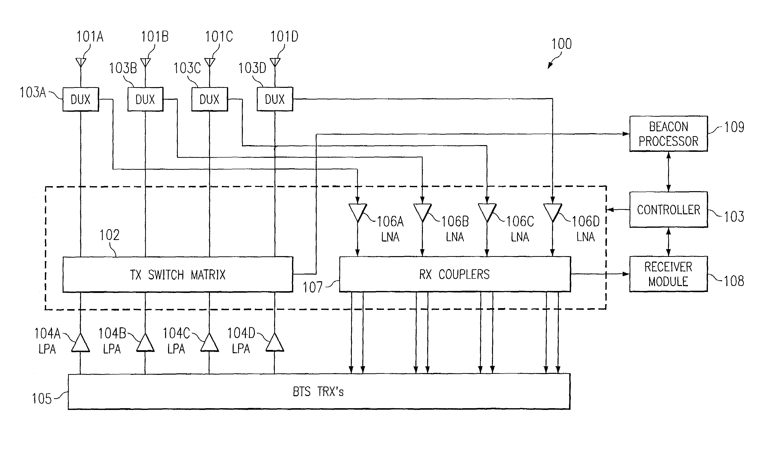
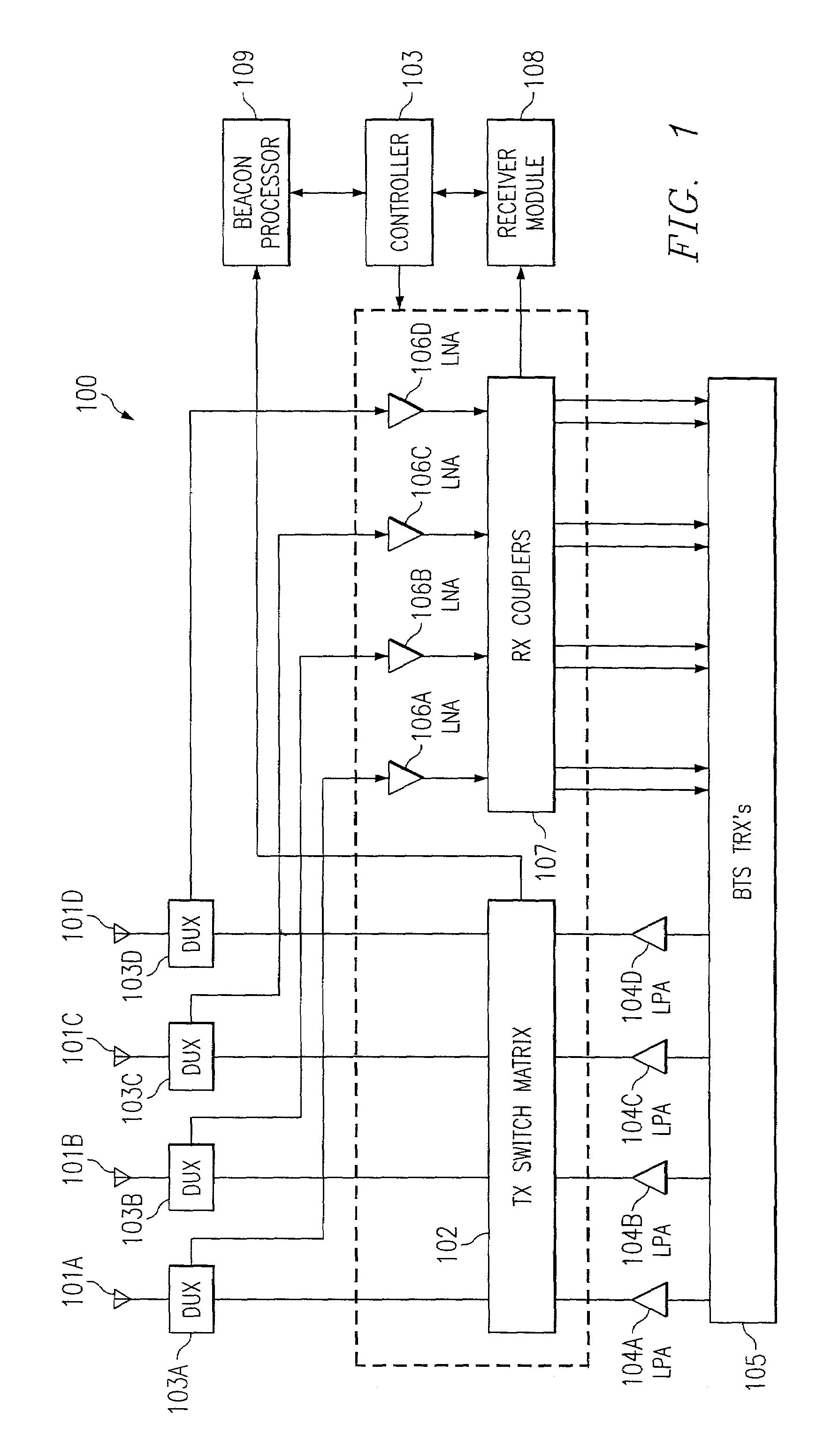
[0022]Referring now to the Drawing, FIG. 1 depicts exemplary wireless communication system 100 according to embodiments of the present invention. Wireless communication system 100 comprises a plurality of antennas 101A–101D. In accordance with embodiments of the present invention, antennas 101A–101D may be disposed to provide approximately a same coverage area. Preferably, antennas 101A–101D are distantly disposed so as the provide diversity against shadow fading. Other diversity techniques may be employed such as polarization diversity or directional diversity. Also, any combination of diversity techniques may be employed. For the present example, four antennas 101A–101D are shown. However, it shall be appreciated that the number of antennas is merely exemplary as other numbers of antennas may be used according to embodiments of the present invention.

[0023]Duplexers 103A through 103B are coupled to antennas 101A through 101D. Duplexers 103A and 103D apply forward-link signals from ...


PUM


Abstract

The present invention is directed to wireless communication, and more particularly, to providing improved signal quality using antenna beam selection and/or switching techniques. Embodiments of the present invention may measure the carrier-to-interference (C/I) level for each channel and for each antenna. Embodiments of the present invention assign forward-link signals to antennas such that only one forward-link signal is transmitted from a respective antenna. Moreover, embodiments prioritize assignment to antennas by the forward-link power, i.e., the forward-link signal associated with the highest power is transmitted from the antenna associated with the best channel quality metric for reverse-link of the respective channel. Additionally, embodiments may employ the assignment scheme with antennas that possess spatial, polarization, and/or directional diversity to minimize the effects of shadow fading.

Description

TECHNICAL FIELD OF THE INVENTION[0001]The present invention is directed to wireless communication, and more particularly, to providing improved signal quality using antenna beam selection and / or switching techniques.BACKGROUND OF THE INVENTION[0002]In typical time division multiple access / time division multiplexing (TDMA / TDM) cellular systems (e.g., IS-136 and Groupe Special Mobile (GSM) systems), a diversity antenna scheme is utilized. For example, a typical cellular site employs a sectorized coverage scheme. For each sector, one transmit and two receive antennas are utilized. The two receive antennas are, for example, placed on a site tower and are separated by a sufficient number of wavelengths to avoid being correlated for the purposes of Raleigh fading. On the reverse-link (i.e., from the subscriber to the cell site receivers), a signal from a subscriber is received by both receive antennas. Both receive antennas are coupled to diversity ports of a receiver before digitally sam...

Claims


Application Information

Patent Timeline
Patent Type & Authority Patents(United States)
IPC IPC(8): H04B1/38H04M1/00
CPCH01Q3/24H04B17/336H04B7/061
Inventor SCHERZER, SHIMON B.
Owner F POSZAT HU
Why Eureka
Try Eureka