
Structural health monitoring (SHM) transducer assembly and system

Inactive Publication Date: 2008-11-27
THE BOEING CO
View PDF3 Cites 62 Cited by
  • Summary
  • Abstract
  • Description
  • Claims
  • Application Information

AI Technical Summary

Benefits of technology

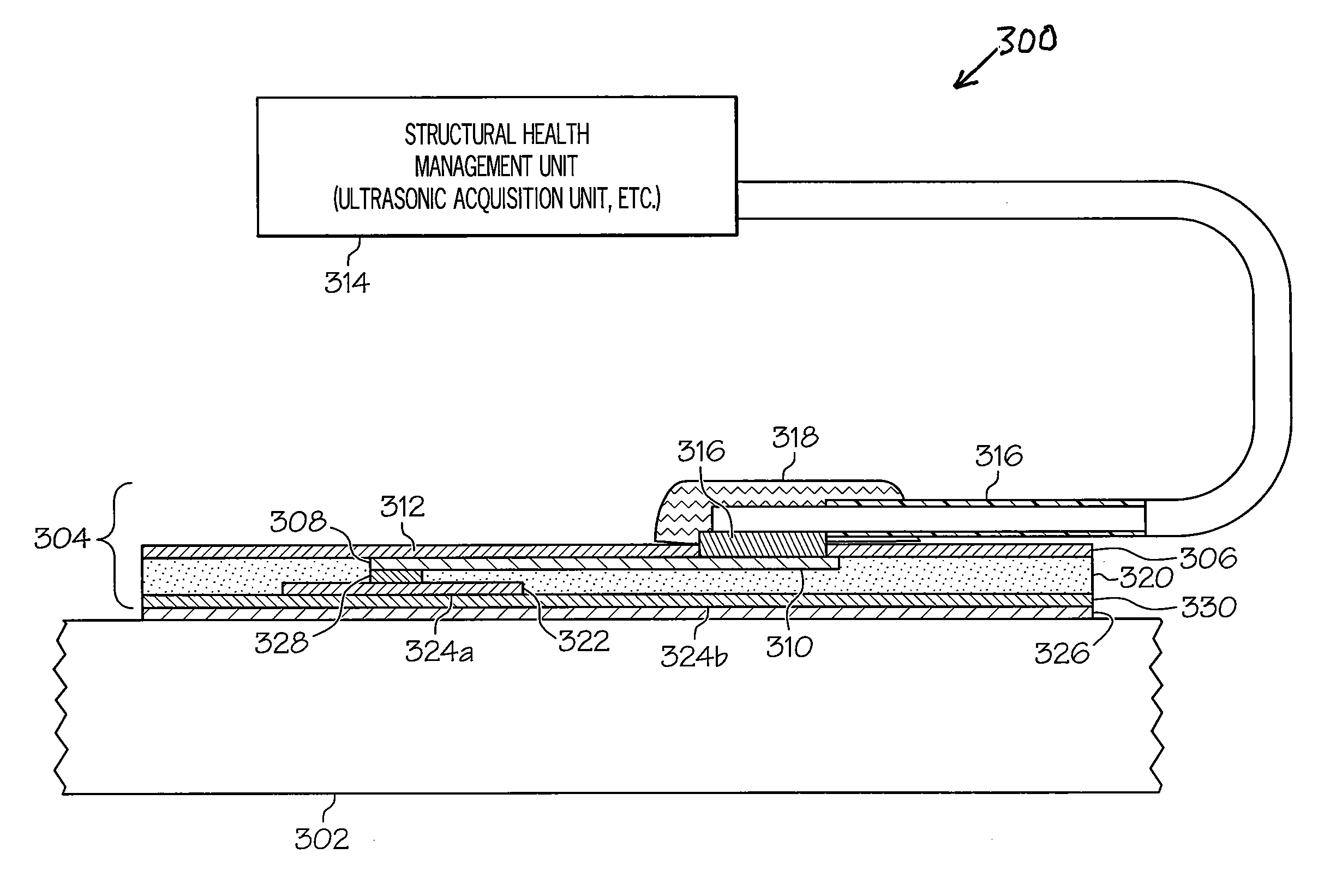
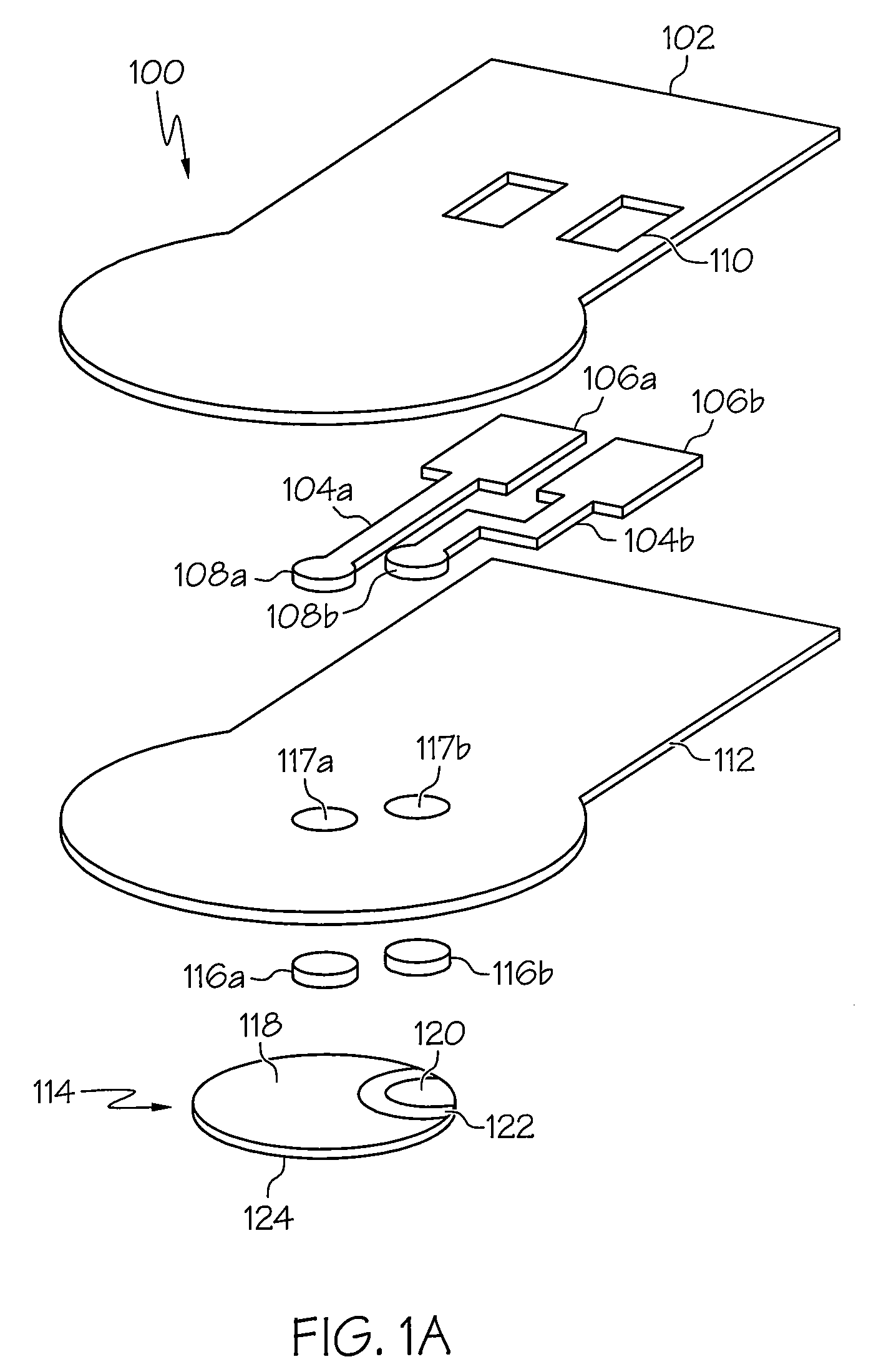
[0004]In accordance with another embodiment of the present invention, a transducer assembly may include a polyimide film and a pair of electrically conductive traces bonded to the polyimide film. Each of the electrically conductive traces may include a first contact pad and a second contact pad. The polyimide film may include a pair of vias or openings formed therein to expose each of the first contact pads for connection to a structural health monitoring unit. A layer of non-conductive adhesive may be attached to the polyimide film and encapsulate the electrically conductive traces in association with the polyimide film. The transducer assembly may also include a flat electromechanical transducer. The layer of non-conductive adhesive may be adapted to attach the flat electromechanical transducer to the polyimide film such that a signal transmitting face of the flat electromechanical transducer forms a substantially flat surface with the non-conductive adhesive layer to prevent any voids when the transducer assembly is attached to an object for actuating and sensing or other monitoring. A pair of electrically conductive adhesive patches may separately connect each of the two contact pads of the electrically conductive traces to the flat electromechanical transducer through a hole in the layer of non-conductive adhesive.

Problems solved by technology

The new materials and new designs may be subject to extreme stresses or potential damage from an impact or other cause.
For example near a fuselage cargo door surround of a commercial aircraft, baggage handlers often inadvertently collide with and cause impact damage to the airplane fuselage.

Method used


Image

  • Structural health monitoring (SHM) transducer assembly and system
  • Structural health monitoring (SHM) transducer assembly and system
  • Structural health monitoring (SHM) transducer assembly and system

Examples


Embodiment Construction

[0012]The following detailed description of embodiments refers to the accompanying drawings, which illustrate specific embodiments of the invention. Other embodiments having different structures and operations do not depart from the scope of the present invention.

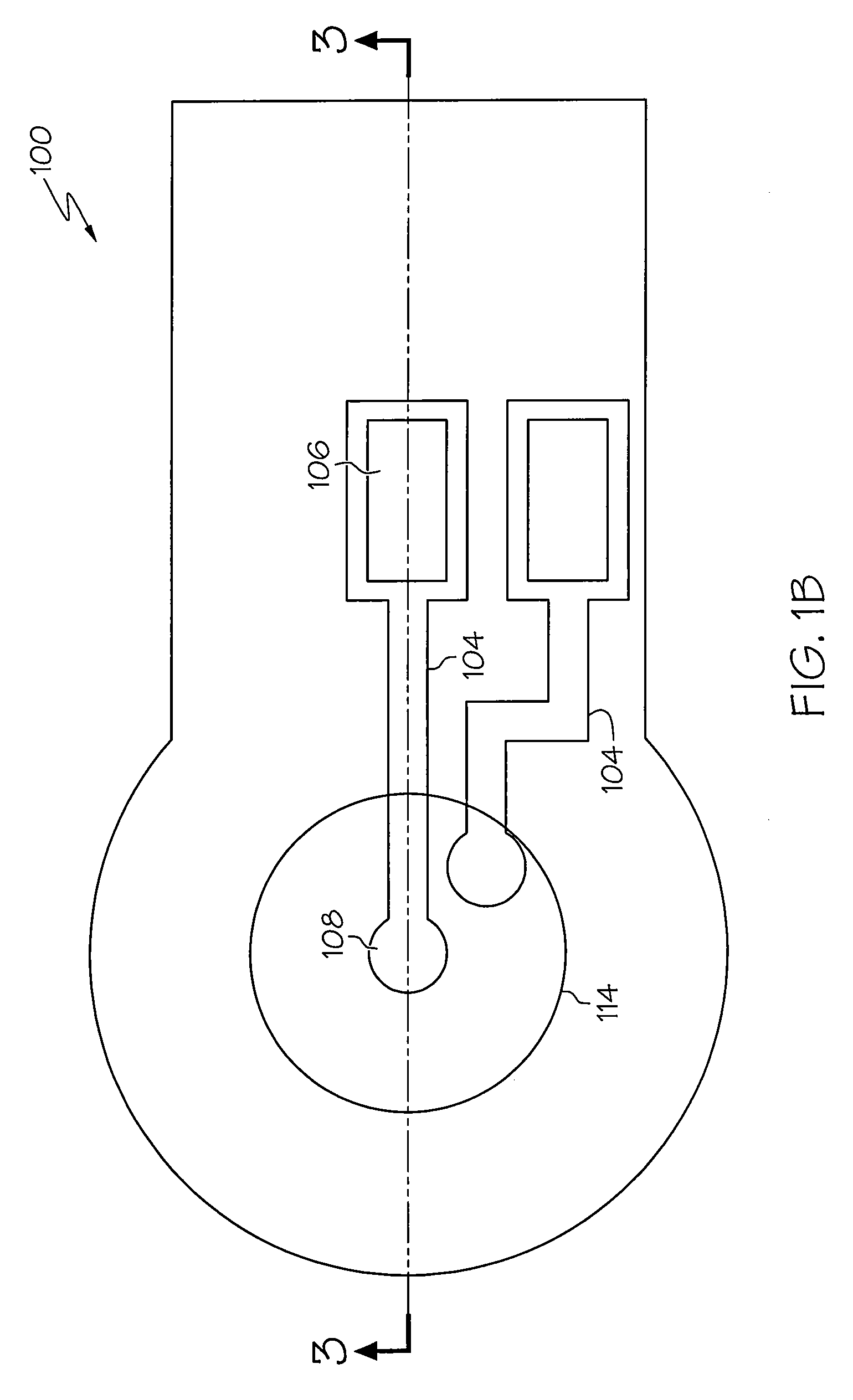
[0013]FIG. 1 is an exploded view of an example of a transducer assembly 100 that may be used for structural health monitoring in accordance with an embodiment of the present invention. The transducer assembly 100 may include a first layer 102 of dielectric material. The first layer 102 of dielectric material may be a polyimide film or similar flexible non-conductive material. The first layer may have a thickness of about 7.5 mils or less. The polyimide film or first layer 102 may be Dupont Pyralux LF9150 or a similar material. Pyralux is a trademark of E.I. Du Pont De Nemours and Company in the United States, other countries or both.

[0014]A pair of electrically conductive traces 104 may be disposed adjacent to, bonded to or...


PUM

PropertyMeasurementUnit
Temperatureaaaaaaaaaa
Thicknessaaaaaaaaaa
Thicknessaaaaaaaaaa

Abstract

A transducer assembly may include a first layer of dielectric material and a pair of electrically conductive traces adjacent to the first dielectric layer. Each of the electrically conductive traces may include a first contact pad and a second contact pad. The first layer of dielectric material may include a pair of vias or openings formed therein to expose each of the first contact pads. A second layer of dielectric material may be attached to the first layer of dielectric material with the pair of electrically conductive traces disposed between the first and second layers of dielectric material. A transducer may be attached to the second layer of dielectric material and each second contact pad may be electrically connected to the transducer.

Description

BACKGROUND OF THE INVENTION[0001]The present invention relates to monitoring structural health of an object, such as an aircraft or other vehicle, and more particularly to a structural health monitoring (SHM) transducer assembly and system that may utilize the SHM transducer assembly.[0002]New, lightweight composite materials, traditional metallic materials, and other materials are being used and optimized in designs more extensively in the aerospace industry for commercial aircraft and other aerospace vehicles, as well as in civil infrastructure, ground transportation, and other industries. The new materials and new designs may be subject to extreme stresses or potential damage from an impact or other cause. For example near a fuselage cargo door surround of a commercial aircraft, baggage handlers often inadvertently collide with and cause impact damage to the airplane fuselage. Any such damage needs to be quickly and efficiently identified, located, and the size and extend determi...

Claims


Application Information

Patent Timeline
IPC IPC(8): G01H11/08H01L41/09H01L41/22
CPCG01M5/00H01L41/0475Y10T29/42H01L41/1132H01L41/053H10N30/875H10N30/88H10N30/302
Inventor KEARNS, JUSTIN D.ANDERSON, DAVID M.
Owner THE BOEING CO
Learn More