
Gene Detection Field-Effect Device And Method Of Analyzing Gene Polymorphism Therewith

Active Publication Date: 2008-11-20
NAT INST FOR MATERIALS SCI
View PDF3 Cites 168 Cited by
  • Summary
  • Abstract
  • Description
  • Claims
  • Application Information

AI Technical Summary

Benefits of technology

[0013]In view of such circumstances, it is an object of the invention in this application to provide a novel gene detection field-effect device and a method of analyzing gene polymorphism therewith that enables detection and analysis of genes with high degree of sensitivity and high degree of accuracy, and reduction of the size and cost of the gene polymorphism analyzing system in comparison with the related art.

Problems solved by technology

It has problems that laser or complex optical system is required, and the system is upsized and expensive.
Therefore, there is a problem in accuracy of the gene polymorphism analysis.
However, in the case of the four systems in Non-Patent Documents 1 to 4, since detection is based on the oxidation-reduction reaction on the metal electrode in principle, there is a problem such that if there exists an oxidizing substance or a reducing substance in a sample (for example, ascorbic acid), an electric current based on oxidation or reduction flows, which hinders detection of gene and results in deterioration of detection accuracy.
Since the electrode reaction is irreversible and non-equilibrium reaction, corrosion of the electrode or generation of gas may be resulted, and consequently, separation of immobilized nucleic acid or impairment of stability of current measurement may be resulted.
Therefore, there is a problem such that the detection accuracy may be deteriorated specifically when measurement is repeatedly performed.
However, since the DNA probe formed on a substrate has the negative electric charge by nature, the amount of change in electric charge by the hybridization of the target gene is small, and hence identification from non-specific adsorption is impossible.
It is also difficult to detect a slight difference (one base is different) between two genes such as the Single Nucleotide Polymorphism (SNP) since both the sensitivity and accuracy (selectivity) are low.

Method used


Image

  • Gene Detection Field-Effect Device And Method Of Analyzing Gene Polymorphism Therewith
  • Gene Detection Field-Effect Device And Method Of Analyzing Gene Polymorphism Therewith
  • Gene Detection Field-Effect Device And Method Of Analyzing Gene Polymorphism Therewith

Examples


example

Example 1

Detection and Analysis of SNP in Factor VII Gene

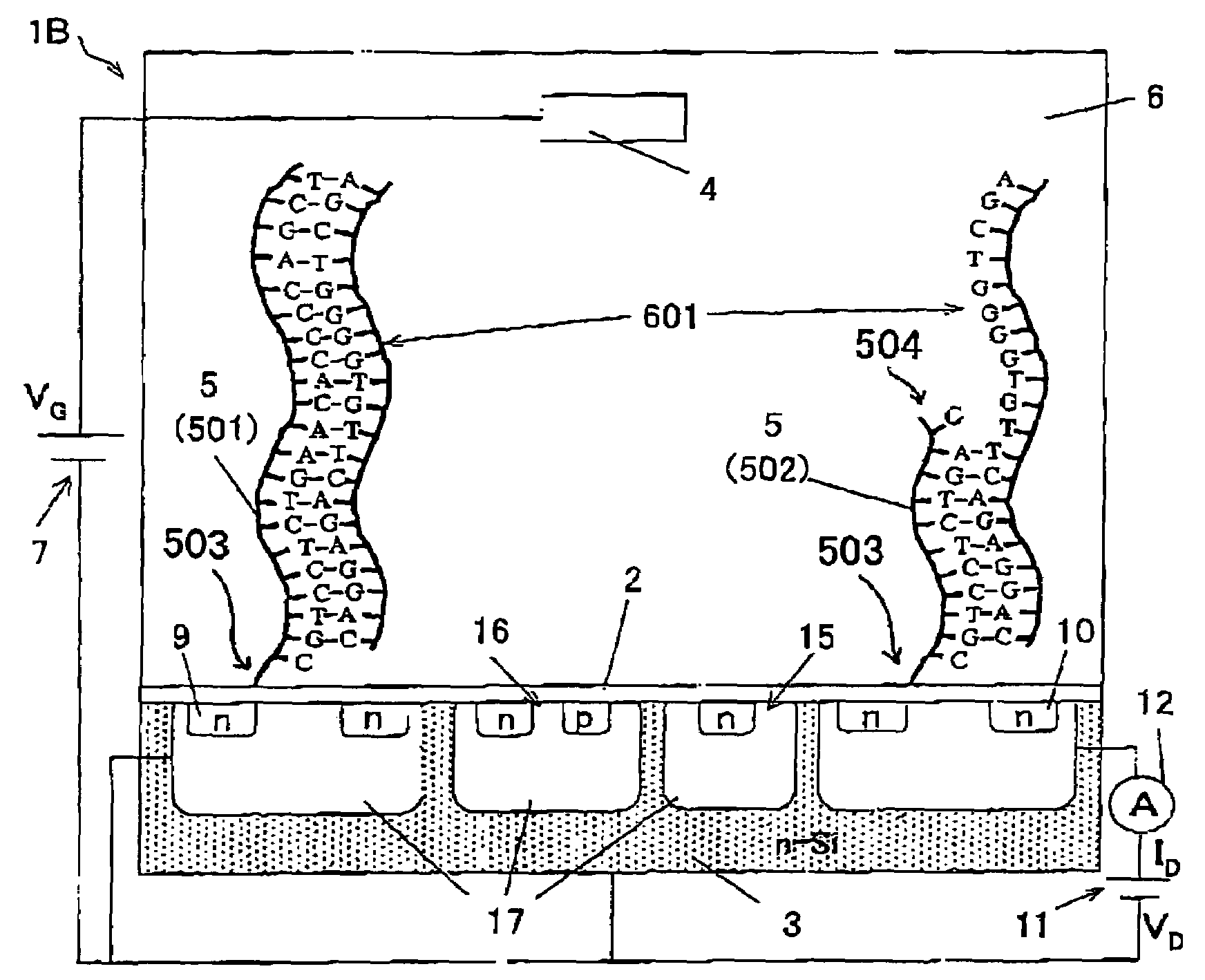
[0137]The Factor VII gene as one of blood coagulation genes includes a plurality of single nucleotide polymorphisms (SNP) existing therein. It is known that the wild-type (normal) of one of the SNPs at a position −122 is thymine (T) and the mutant-type thereto is cytosine (C). In order to detect the SNP at the portion −122 of the Factor VII gene, two types of nucleic acid probes formed of 11 bases, which correspond to the wild-type and the mutant-type, respectively were synthesized. The base sequences thereof were as follows, in which a sequence number 1 designates a wild-type nucleic acid probe and a sequence number 2 designates a mutant-type nucleic acid probe.

Wild-type nucleic acid probe: 5′-CGTCCTCTGAA-3′ (sequence No. 1)

Mutant-type nucleic acid probe: 5′-CGTCCTCTGAG-3′ (sequence No. 2)

[0138]In this example, the nucleic acid probes were synthesized so that the base of the SNP portion corresponds to a 3′ terminal end of the...

example 2

When Peptide Nucleotide Acid, PNA was Used in Detection of SNP in Factor VII Gene

[0146]In the example 1 shown above, the double strand nucleus acid with higher stability can be formed by using Peptide Nucleotide Acid, PNA as the nucleic acid probe to be immobilized to the gate insulation film area of the gene detection field-effect transistor.

[0147]Therefore, in this example, Peptide Nucleotide Acid (PNA) was used as the nucleic acid probe although the basic characteristics are substantially the same as the example 1.

[0148]Consequently, in the case of the sample containing the wild-type homozygote, the output of the transistor in which the wild-type PNA probe was immobilized was changed by 23 mV, while the output of the transistor in which the mutant-type PNA probe was immobilized was changed by 4 mV. In the case of the sample containing the wild-type and mutant-type heterozygote, the output of the gene detection field-effect transistors in which the wild-type and mutant-type PNA pr...

example 3

SNP Detection of Alcohol Dehydrogenase Related Gene

[0154]It is known that there exists the single nucleotide polymorphism (SNP) in the alcohol dehydrogenase related gene. The nucleic acid probe is designed so that the SNP portion corresponds to the base at the 3′ terminal end. The base at the SNP portion is thymine (T) in the wild-type and cytosine (C) in the mutant-type, and the base sequences of the nucleic acid probes corresponding thereto are shown below. The wild-type nucleic acid probe in this example is shown by the sequence No. 3, and the mutant-type nucleic acid probe is shown by the sequence No. 4.

The wild-type nucleic acid probe: 5′-CATACACTA-3′ (sequence No. 3)

The mutant-type nucleic acid probe: 5′-CATACACTG-3′ (sequence No. 4)

[0155]In this example, the basic configuration and the procedure of experiment are the same as in the example 1 and the example 2.

[0156]In this example, for example, as shown in FIG. 7 described above, the gene detection field-effect transistor in ...


PUM

PropertyMeasurementUnit
Elongationaaaaaaaaaa

Abstract

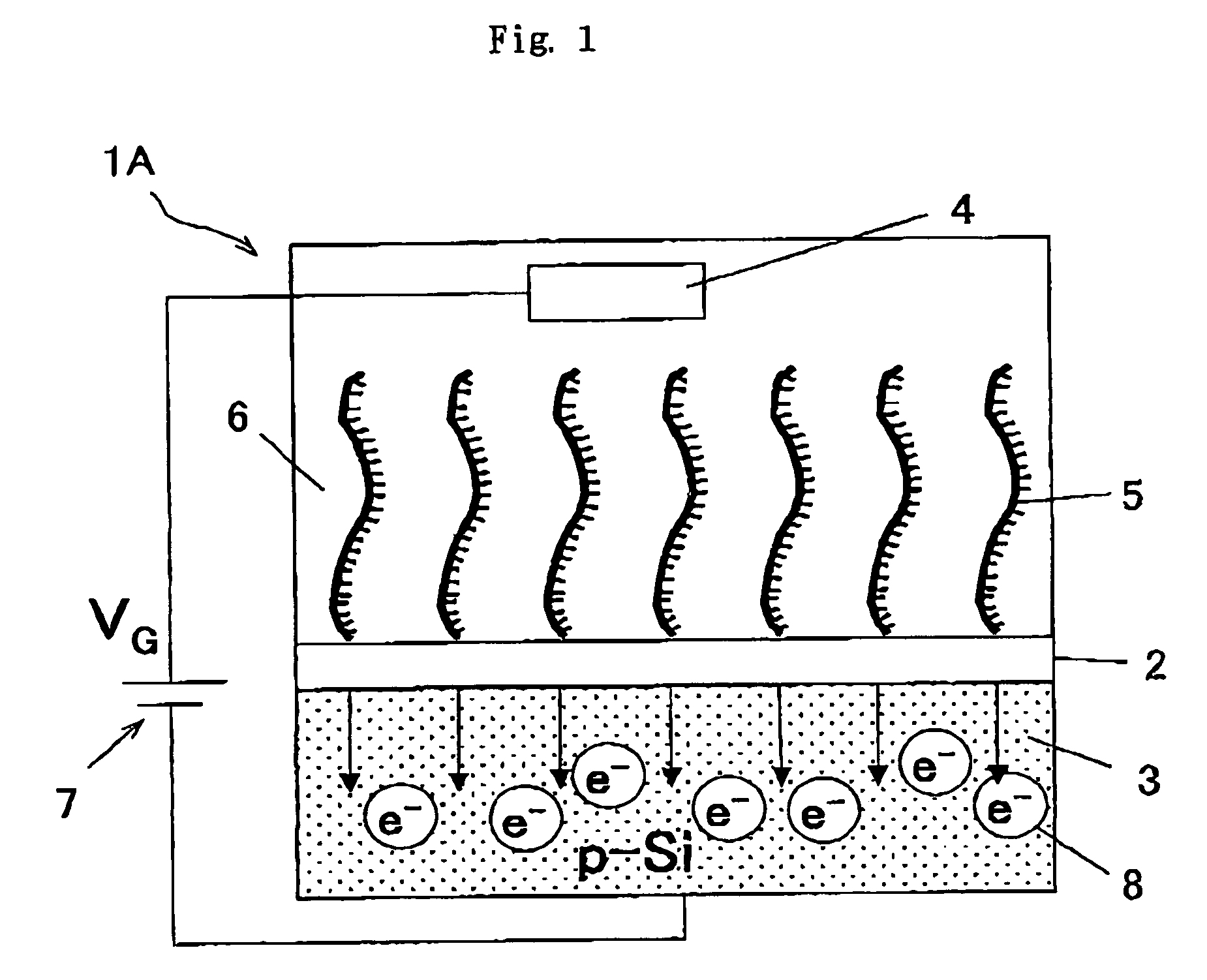
A gene detection field-effect device provided with an insulation film (2), a semiconductor substrate (3), and a reference electrode (4), includes:(a) the insulation film (2) including a nucleic acid probe (5) immobilized on one of the surfaces thereof and is in contact with a sample solution (6) containing at least one type of a target gene (601) for detection and analysis; (b) the semiconductor substrate (3) being installed so as to abut against the other surface of the insulation film (2); and (c) the reference electrode (4) being provided in the sample solution (6).

Description

TECHNICAL FIELD[0001]The invention in this application relates to a gene detection field-effect device and a method of analyzing gene polymorphism therewith. More specifically, the invention in this application relates to a novel gene detection field-effect device and a method of analyzing gene polymorphism therewith which enables detection and analysis of genes with high degree of sensitivity and high degree of accuracy, and reduction of the size and cost of a gene polymorphism analyzing system in comparison with the related art.BACKGROUND ART[0002]Under the circumstance such that decoding of the whole base sequence of human genome is terminated and decoding of base sequence for genome of other living organisms is in breakthrough, a huge amount of base sequence information is being accumulated. It seems that a gene-related technology will be dramatically developed in a wide range of fields such as diagnosis of various diseases, development of medicaments, breed improvement of agric...

Claims


Application Information

Patent Timeline
IPC IPC(8): C12Q1/68C12M1/00G01N33/53C12N15/09G01N27/414G01N27/416
CPCC12Q1/6825C12Q2600/156G01N27/4145C12Q2565/607C12Q2565/537
Inventor MIYAHARA, YUJISAKATA, TOSHIYA
Owner NAT INST FOR MATERIALS SCI
Learn More