
Method and Apparatus for High Temperature Heat Treatment of Combustible Material in Particular Waste

Inactive Publication Date: 2008-11-20
SCOUTECH
View PDF21 Cites 6 Cited by
  • Summary
  • Abstract
  • Description
  • Claims
  • Application Information

AI Technical Summary

Benefits of technology

[0010]A feature of the present invention provides a waste heat treatment method that provides a strong reduction of the pollutants present in the flue gas with a considerable energy saving with respect to the solutions of prior art.
[0012]Another feature of the present invention provides such a waste heat treatment method that allows obtaining an optimal recovering of the energy content of said waste.
[0024]Advantageously, a step is provided of feeding the combustible material in the pyrolysis chamber by forcing the combustible material through a tapered duct in order to reduce its volume. This avoids dangerous backfire, provides a semi-combustion of the combustible material and assists a measurement of its composition, in particular on the content of carbon in order to adjust the flows and the temperature in the different chambers of the apparatus.

Problems solved by technology

Either solution has problems of environmental impact.
In case of waste burying, the risk is high of polluting for a very long time the underlying ground water table owing to percolates; whereas, in case of burning, even if macro-pollutants such as particulates and smoke can be retained, the amount of micro-pollutants introduced in the environment is high.
In particular, the presence of dioxins and furans in the exhausted flue gas causes a strong environmental impact of the existing processes.
Alternatively, the resulting dioxins and the furans can be filtered with the aid of activated carbon (with very high costs of operation) or other filtering systems.
However, the existing apparatus for burning waste, for example of the type described in U.S. Pat. No. 3,759,036 and U.S. Pat. No. 4,732,092, is not always capable of avoiding the emission of pollutants so that the pollutants fall within the limits provided by the environmental laws.
In other cases, instead, it is possible to fall within said limits only with the use of structurally complicated and expensive apparatus, in particular concerning the energy necessary for completing the process.

Method used


Image

  • Method and Apparatus for High Temperature Heat Treatment of Combustible Material in Particular Waste
  • Method and Apparatus for High Temperature Heat Treatment of Combustible Material in Particular Waste
  • Method and Apparatus for High Temperature Heat Treatment of Combustible Material in Particular Waste

Examples


Embodiment Construction

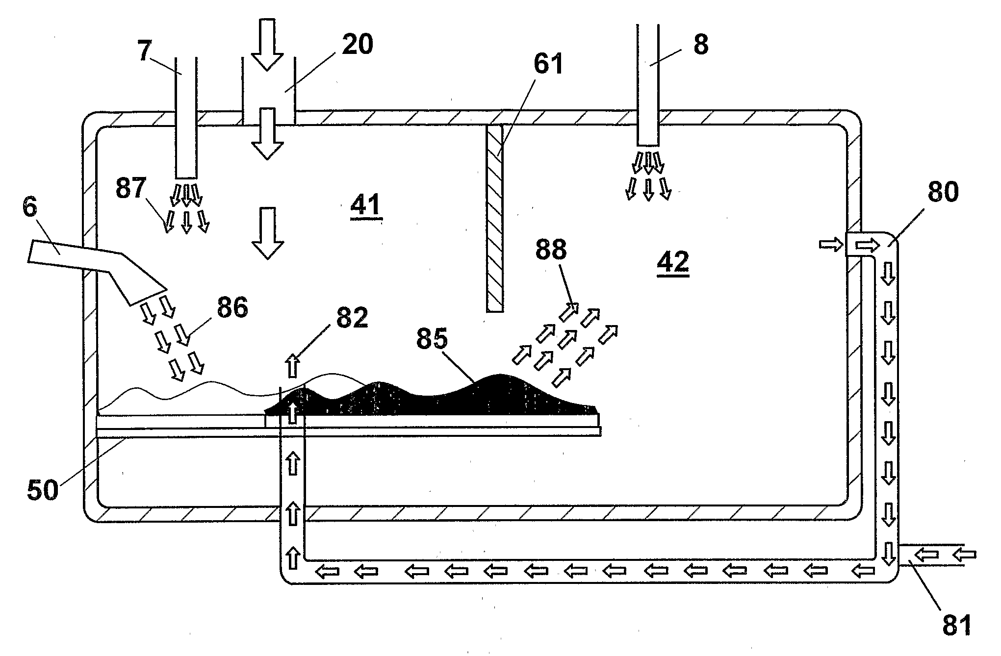
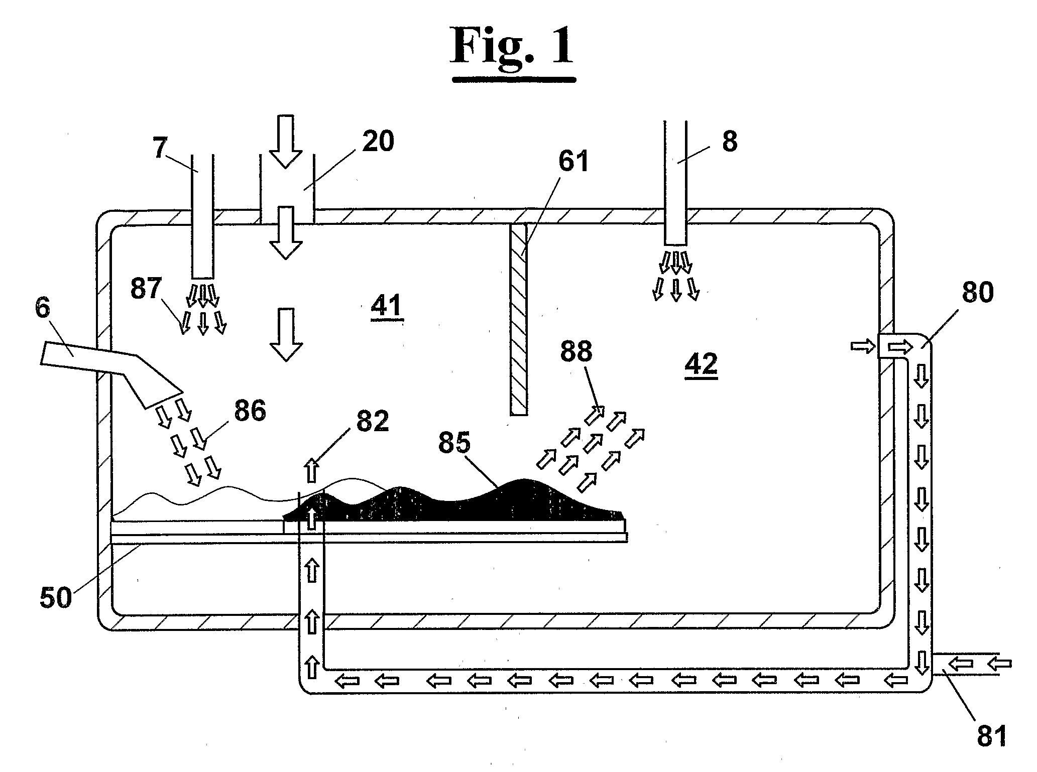
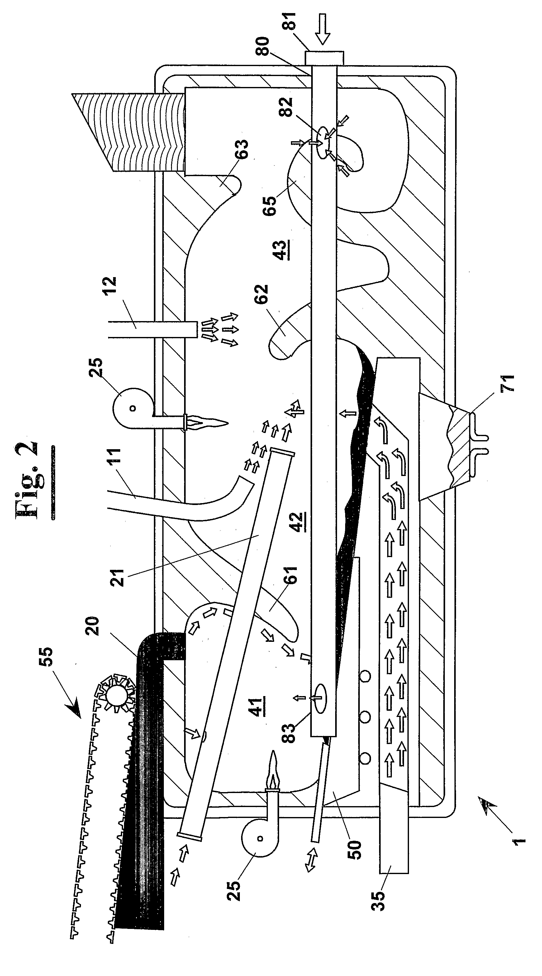
[0041]In FIG. 1, a first exemplary embodiment is diagrammatically shown of an apparatus 1, according to the present invention, for high temperature heat treatment of combustible material, in particular municipal solid waste (waste products), or combustible waste of a desired nature, provided that the combustible waste is a solid and not explosive waste. The apparatus comprises a pyrolysis chamber 41, where the material 85 to treat is heated in a reducing environment, up to a temperature suitable for making a first molecular break of the substances present in the material, and a combustion chamber 42 within which a full combustion is achieved of the combustible material by introducing a predetermined flow of oxygen 8. The full combustion of the combustible material is carried out only in combustion chamber 42 of the apparatus 1 and produces, in particular, gas at high temperature that is directed back to pyrolysis chamber 41 in order to remarkably raise the temperature of pyrolysis. ...


PUM


Abstract

An apparatus (1) for high temperature heat treatment of combustible material comprising a pyrolysis chamber (41) and a combustion chamber (42). The full combustion of the combustible material produces gas at high temperature that is sent to the pyrolysis chamber in order to raise the temperature of pyrolysis. This associated to the introducing water vapour, through a duct (6), and of air, through a duct (7), in pyrolysis chamber (41) produce semiwater gas that is then burnt in combustion chamber (42) by feeding a current (8) of a fluid containing oxygen to raise the combustion temperature in order to carry out the process to temperature that assures the molecular break of the totality of the toxic substances.

Description

PRIORITY CLAIM[0001]This patent application is a U.S. National Phase of International Application No. PCT / EP2005 / 005996, filed Jun. 3, 2005, which claims priority to European Patent Application No. 04425425.8, filed Jun. 10, 2004, the disclosures of which are incorporated herein by reference in their entirety.FIELD OF THE INVENTION[0002]The present invention relates to an apparatus for high temperature heat treatment of combustible material, in particular industrial and municipal waste of any kind, even toxic or noxious waste, for minimizing the dangerousness of the combustion products. Furthermore, the invention relates to a pyrolytic converter for recovering the energy content of the waste.BACKGROUND OF THE INVENTION[0003]It is well known that systems traditionally used for waste disposal, in particular municipal solid waste, provide either burying or burning the waste. Either solution has problems of environmental impact. In case of waste burying, the risk is high of polluting fo...

Claims


Application Information

Patent Timeline
IPC IPC(8): F23B90/00F23G5/027F23G5/10F23G5/16F23G5/50F23G7/10F23G7/12F23J15/04
CPCF23G5/0273F23G5/10F23G5/16F23G5/50F23G7/10F23G7/12F23G2202/104F23G2203/101F23G2203/803F23G2207/101F23G2207/102F23G2207/108F23G2209/20F23G2209/22F23G2209/261F23G2209/262F23G2209/281F23G2900/00001F23J15/04F23J2900/01005F23L2900/07009
Inventor MORANDI, ENZO
Owner SCOUTECH
Learn More