
Radio Station and Method of Operating a Radio Station

Active Publication Date: 2008-10-30
KONINKLIJKE PHILIPS ELECTRONICS NV
View PDF19 Cites 24 Cited by
  • Summary
  • Abstract
  • Description
  • Claims
  • Application Information

AI Technical Summary

Benefits of technology

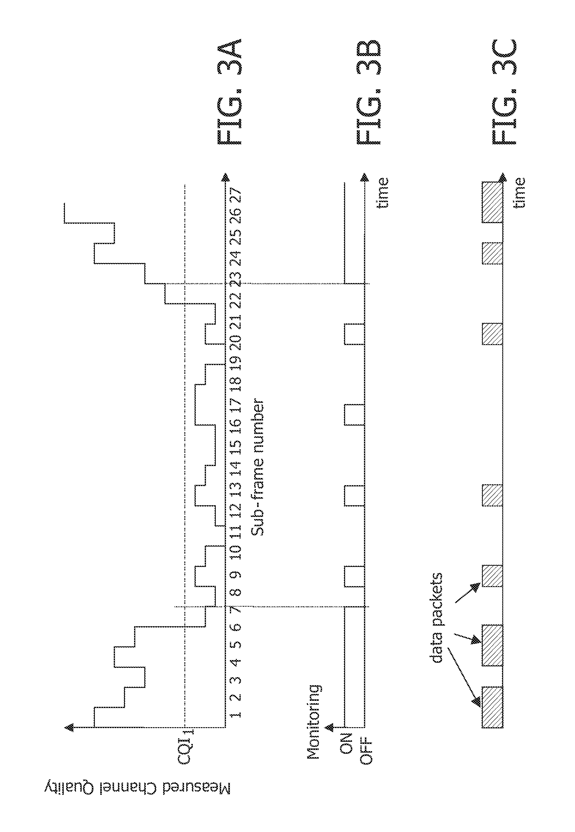
[0008]According to a first aspect of the invention there is provided a method of operating a radio station, comprising:monitoring either continuously or intermittently a first channel for an indication of a transmitted data signal;measuring the quality of a second channel;transmitting indications of the measured quality;comparing the measured quality with a first quality threshold; andin response to the measured quality falling below the first quality threshold, reducing the proportion of time spent monitoring the first channel by introducing or increasing time periods when no monitoring takes place.
[0022]According to a fourth aspect of the invention there is provided a radio station, comprising:transmitter means adapted to transmit data packets to a receiving station;receiver means adapted to receive from the receiving station indications of measured channel quality; andcontrol means adapted to, in response to the measured quality falling below a first quality threshold, reduce the proportion of time spent transmitting the data packets to the receiving station by introducing or increasing time periods between transmitting the data packets.

Problems solved by technology

Receiving and decoding the HS-SCCH control channels consumes energy in the receiver and processor of the MS.
However, a relatively long signalling process is then required to move the MS back to a state where it can receive data packets, which increases the delay for packet transmission and can have an adverse effect on user experience.
However, this restriction reduces the effectiveness of the scheduling algorithm employed by the BS, as the BS has less freedom to transmit data packets on occasions when the channel conditions to that MS are most suitable.

Method used


Image

  • Radio Station and Method of Operating a Radio Station
  • Radio Station and Method of Operating a Radio Station
  • Radio Station and Method of Operating a Radio Station

Examples


Embodiment Construction

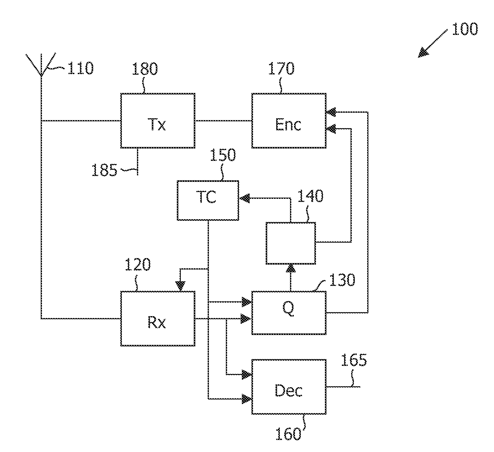
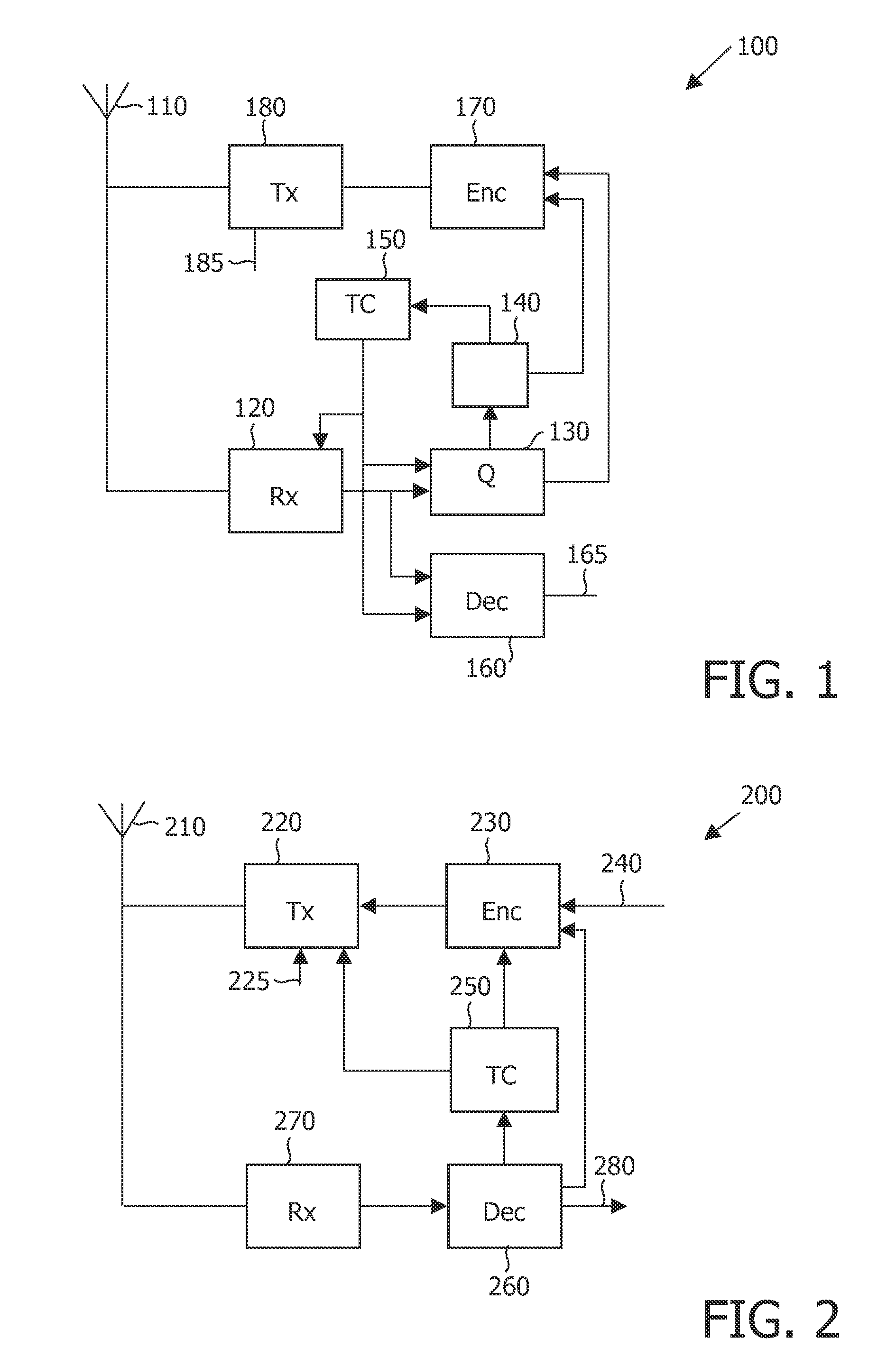
[0027]Referring to FIG. 1, there is illustrated a block schematic diagram of a receiving radio station 100 for receiving data packets. It comprises an antenna 110 coupled to an input of a receiver (Rx) 120 for receiving radio signals. An output of the receiver 120 is coupled to an input of a quality measurement stage (Q) 130 for measuring the quality of received signals. The output of the receiver 120 is coupled to an input of a decoder (Dec) 160 for decoding received signals, including an indication that a data packet is being transmitted, the data packets themselves and other signals. Decoding may include determining whether a received signal includes an address of the radio station 100. The decoder 160 has an output 165 for delivering received and decoded data to an application (not illustrated). The decoder 160 may also generate acknowledgements for transmission to indicate successful receipt of a data packet or to request retransmission of a data packet.

[0028]An output of the q...


PUM


Abstract

A first radio station (100) monitors, either continuously or intermittently, a channel for an indication of a transmitted data packet and measures the quality of the channel. The first radio station (100) transmits indications of the measured quality and when the measured quality falls below a quality threshold, it reduces the proportion of time spent monitoring the channel by introducing or increasing time periods when no monitoring takes place, and subsequently increases the time spent monitoring when the quality recovers. A second radio station (200) transmits data packets to the first radio station (100) and receives the indications of measured channel quality. When the measured quality falls below the quality threshold, the second station reduces the proportion of time spent transmitting the data packets to the first radio station (100) by introducing or increasing time periods between transmitted the data packets.

Description

FIELD OF THE INVENTION[0001]The invention relates to a method of operating a radio station and to a radio station. The invention has particular, but not exclusive, application to mobile communication systems such as UMTS (Universal Mobile Telecommunication System), especially in relation to the HSDPA (High-Speed Downlink Packet Access) feature of UMTS.BACKGROUND OF THE INVENTION[0002]In the current High-Speed Downlink Packet Access (HSDPA) feature of UMTS, mobile stations (MSs) make periodic measurements of the received downlink channel quality. These measurements are reported to the serving base station (BS) in the form of indications of a modulation and coding scheme (MCS) that the MS estimates it can decode with a certain probability under the measured channel conditions. These measurement reports are known in UMTS as Channel Quality Indicators (CQI). In each sub-frame, the serving BS uses the CQI reports received from different MSs to select a subset of the MSs (typically those ...

Claims


Application Information

Patent Timeline
IPC IPC(8): H04B7/00H04B1/707H04B1/7097H04J13/00
CPCH04B17/0087H04B17/382H04B17/24
Inventor BAKER, MATTHEW P.J.MOULSLEY, TIMOTHY J.
Owner KONINKLIJKE PHILIPS ELECTRONICS NV
Learn More