
Video decompression, de-interlacing and frame rate conversion with frame buffer compression

a frame rate conversion and video decompression technology, applied in the field of digital video decompression, deinterlacing and frame rate conversion with frame buffer compression, can solve the problems of image quality degradation, high semiconductor die area and cost, and the dominance of reference memory, so as to achieve the effect of reducing the cost of image quality, discrepancy and quality degradation

Inactive Publication Date: 2008-10-30
TAIWAN IMAGINGTEK
View PDF6 Cites 18 Cited by
  • Summary
  • Abstract
  • Description
  • Claims
  • Application Information

AI Technical Summary

Benefits of technology

"The present invention is related to a method of digital video de-interlacing and frame rate conversion. The method reduces the semiconductor die area and cost by compressing and decompressing the reference frame buffer. It also reduces the memory density and input / output bandwidth requirement for off-chip memory. The method achieves good image quality by compressing and decompressing the video frames used as reference for video de-interlacing. The motion vectors embedded in the video stream can be decoded and saved into a temporary buffer for later use in the compression process. The method can be implemented in parallel using multiple video decoding engines and a frame buffer inter-frame compression mode. The method also allows for separate writing of the recompressed lines of multiple frames and the use of interpolation means for de-interlacing and frame rate conversion."

Problems solved by technology

In compressing or decompressing the P-type or B-type of video frame or block of pixels, the referencing memory dominates high semiconductor die area and cost.
If the referencing frame is stored in an off-chip memory, due to I / O data pad limitation of most semiconductor memories, accessing the memory and transferring the pixels stored in the memory becomes bottleneck of most implementations.
In MPEG2 TV application, a Frame of video is divided to be “odd field” and “even field” with each field being compressed separately which causes discrepancy and quality degradation in image when 2 fields are combined into a frame before display.

Method used


Image

  • Video decompression, de-interlacing and frame rate conversion with frame buffer compression
  • Video decompression, de-interlacing and frame rate conversion with frame buffer compression
  • Video decompression, de-interlacing and frame rate conversion with frame buffer compression

Examples


Embodiment Construction

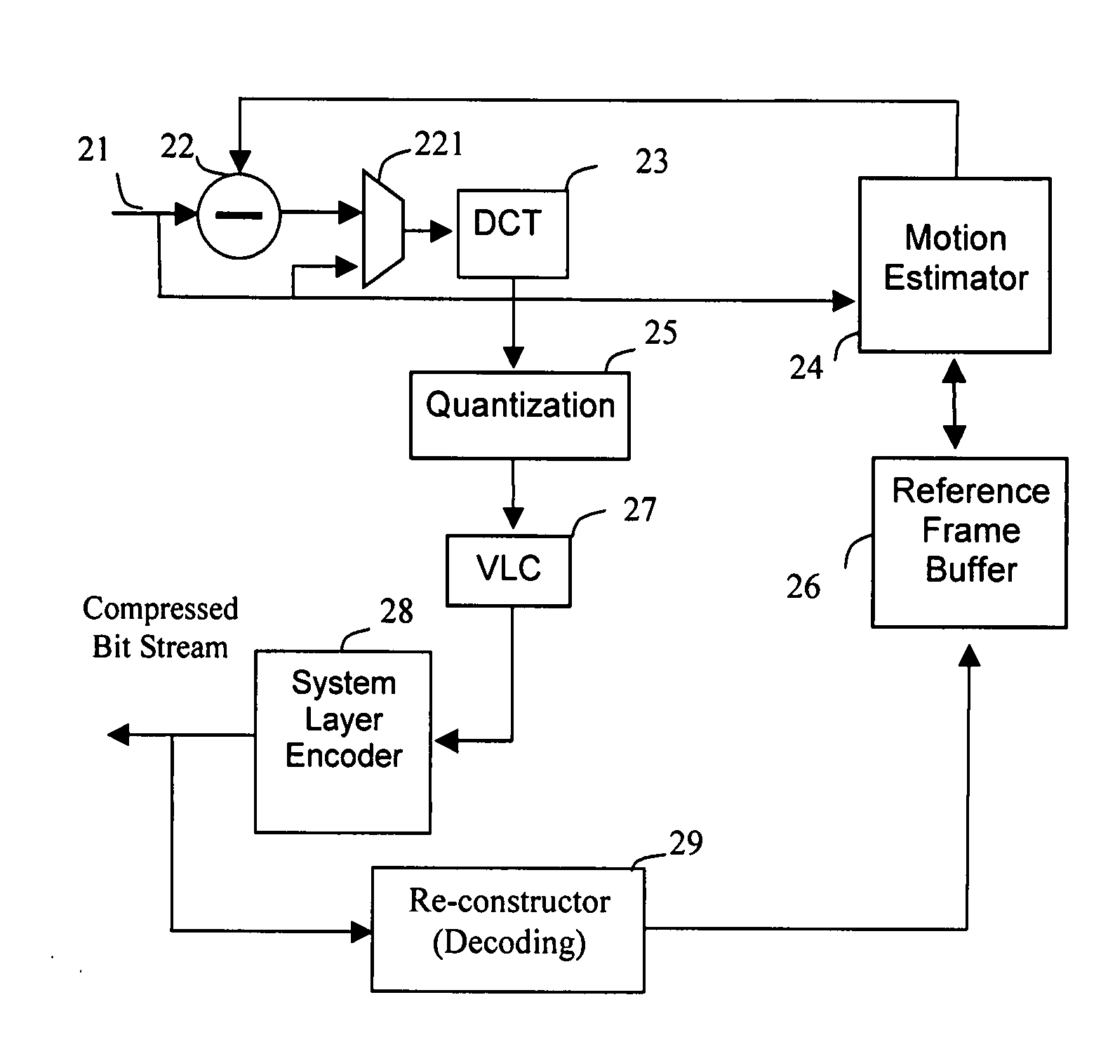
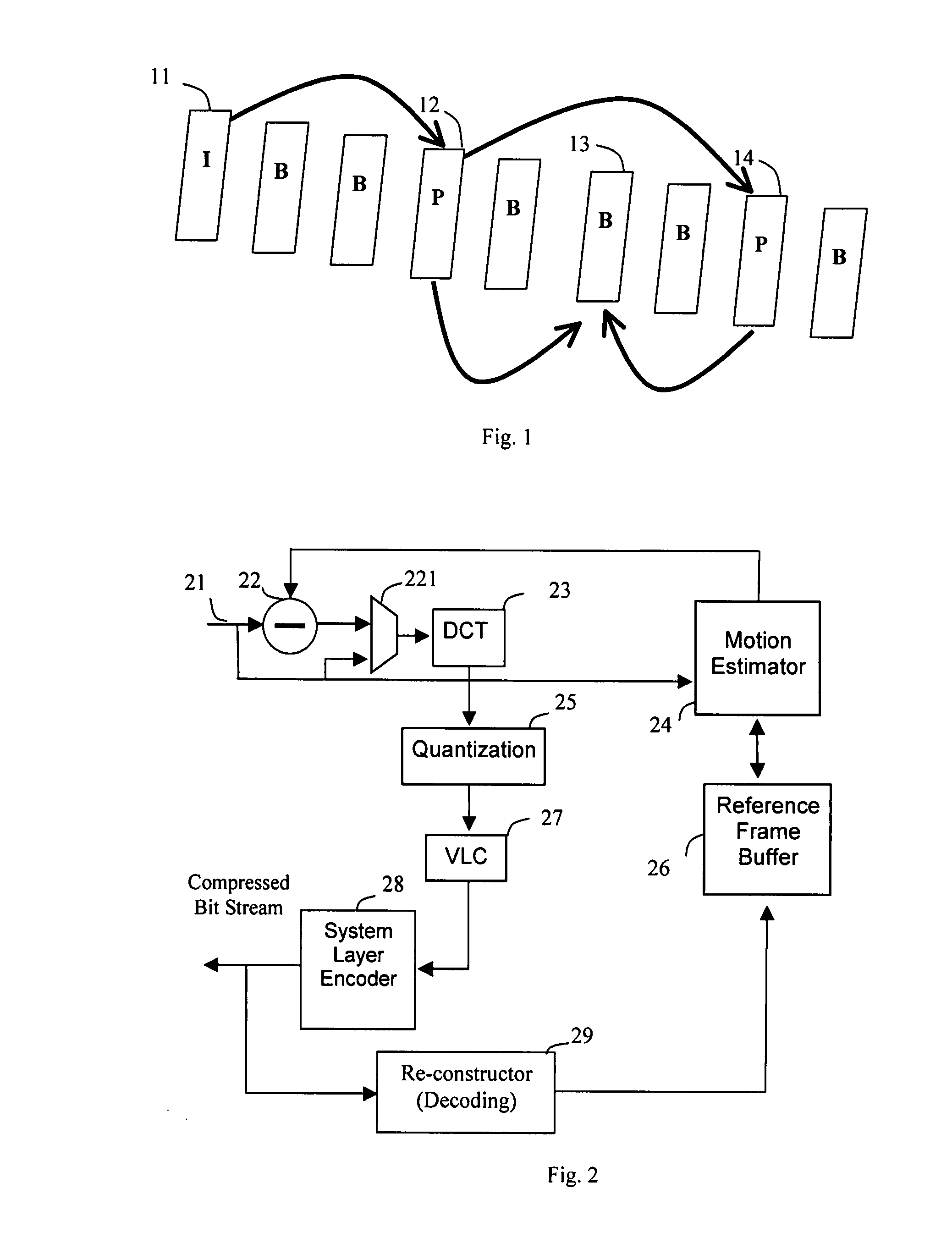
[0041]There are essentially three types of picture coding in the MPEG video compression standard as shown in FIG. 1. I-frame 11, the “Intra-coded” picture, uses the block of pixels within the frame to code itself. P-frame 12, the “Predictive” frame, uses previous I-frame or P-frame as a reference to code the differences between frames. B-frame 13, the “Bi-directional” interpolated frame, uses previous I-frame or P-frame 12 as well as the next I-frame or P-frame 14 as references to code the pixel information.

[0042]In most applications, since the I-frame does not use any other frame as reference and hence no need of the motion estimation, the image quality is the best of the three types of pictures, and requires least computing power in encoding since no need for motion estimation. The encoding procedure of the I-frame is similar to that of the JPEG picture. Because of the motion estimation needs to be done in referring both previous and / or next frames, encoding B-type frame consumes ...


PUM


Abstract

Inter-frame and intra-frame block pixel compression means are applied to re-compress the decompressed video field / frame for future digital video decompression, de-interlacing and frame conversion. The motion vectors, MVs, decompressed from the compressed video field / frame are temporarily saved in a buffer for future inter-frame coding of block by block re-compression. If the input video frames are uncompressed or decompressed fields / frames, they will be compressed before saving into an off-chip frame buffer, later, the accessed lines of compressed pixels of at least two fields / frames will be used for de-interlacing and frame rate conversion. If the corresponding MV is out of the predetermined threshold, inter-frame coding will be skipped and only intra-frame coding is applied.

Description

BACKGROUND OF THE INVENTION[0001]1. Field of Invention[0002]The present invention relates to digital video decompression, de-interlacing and frame rate conversion with referencing frame buffer compression. And, more specifically to an efficient image buffer compression for video stream decompression, de-interlacing method and image interpolation which sharply reduces the IO bandwidth requirement of the off-chip frame buffer or reduces the dies area of on-chip line buffer.[0003]2. Description of Related Art[0004]ISO and ITU have separately or jointly developed and defined some digital video compression standards including MPEG-1, MPEG-2, MPEG4, MPEG-7, H.261, H.263 and H.264. The success of development of the video compression standards fuels wide applications which include video telephony, surveillance system, DVD, and digital TV. The advantage of digital image and video compression techniques significantly saves the storage space and transmission time without sacrificing much of th...

Claims


Application Information

Patent Timeline
Patent Type & Authority Applications(United States)
IPC IPC(8): H04N7/12
CPCH04N7/012H04N19/85H04N9/8042H04N19/139H04N19/176H04N19/61H04N19/107H04N19/132H04N19/152H04N19/44H04N19/433H04N19/436H04N19/55H04N19/587H04N7/0135
Inventor SUNG, CHIH-TA STAR
Owner TAIWAN IMAGINGTEK
Learn More