Specific absorption rate measurement system and method
a measurement system and absorption rate technology, applied in the field of measurement systems, can solve the problems of increasing measurement time, difficult to enable a highly accurate estimation of the 3-dimensional sar distribution, complicated scanning method and/or arrangement of the sensor apparatus, etc., and achieves the reduction of the period of time, simplified sar estimation procedures and the measurement system, and highly accurate 3-dimensional sar distribution.
- Summary
- Abstract
- Description
- Claims
- Application Information
AI Technical Summary
Benefits of technology
Problems solved by technology
Method used
Image
Examples
example 1
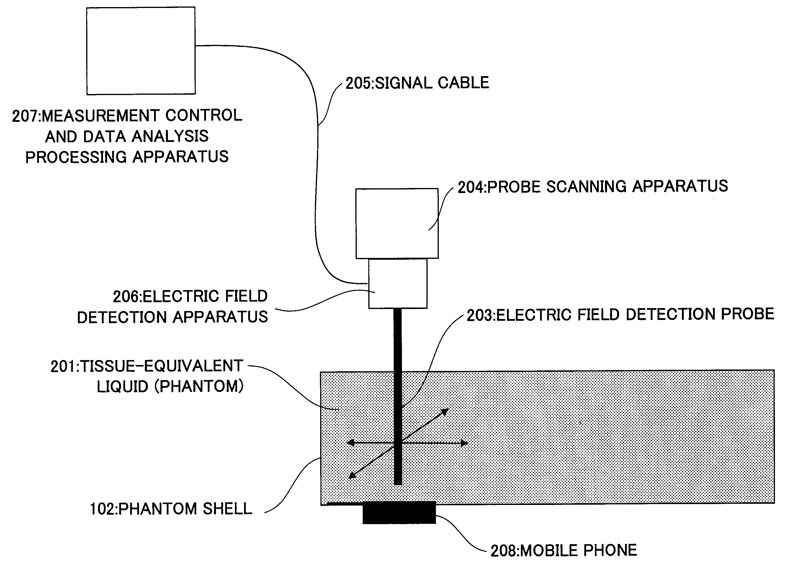
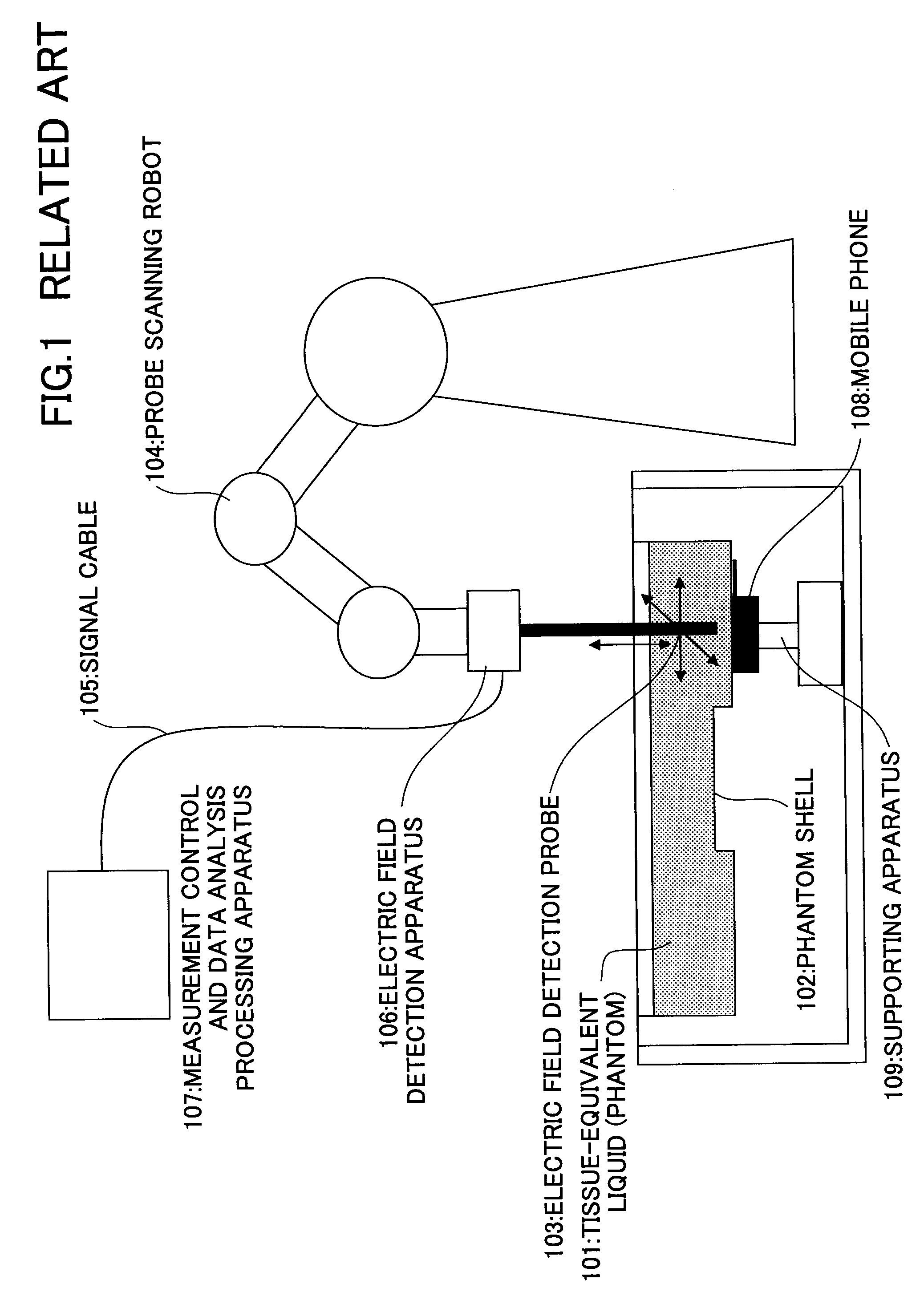
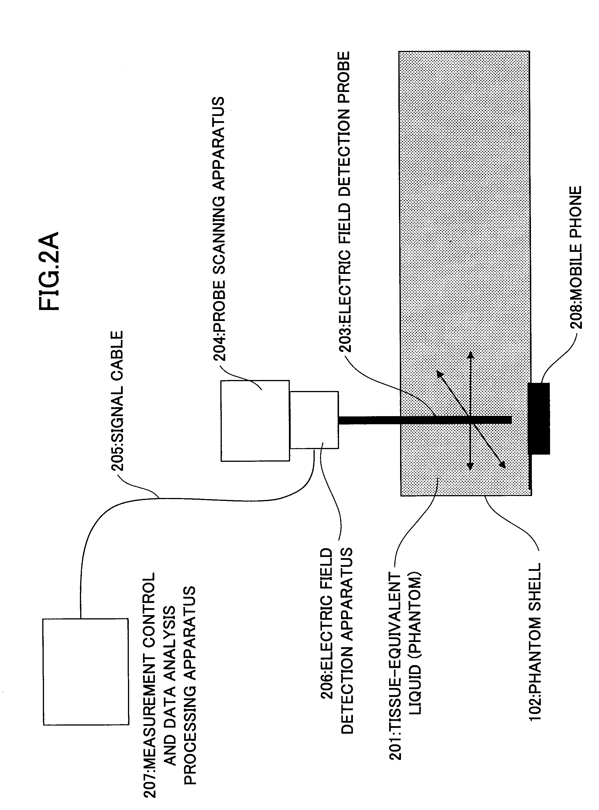
[0050]FIG. 2A is a schematic view of a fast SAR measurement system according to a first example of the present invention. As shown, the fast SAR measurement system includes tissue-equivalent liquid (phantom) 201 having predetermined dielectric constants so as to simulate a human body, a phantom shell 202, an electric probe 203, a probe scanning apparatus 204, a signal cable 205, an electric field detection apparatus 206, and a measurement control and data analysis processing apparatus 207. In this system, a radio terminal apparatus such as a mobile phone 208 or the like is attached on the phantom shell 202 as shown FIG. 2A, and the electric field generated in the phantom 201 is measured. The radio terminal apparatus may be, for example but not limited to, a personal digital assistance (PDA), a desk top computer, a hand-held computer, a credit card identification terminal, a camera, and a wearable computer, all of which have a radio communications function or a network connectable fu...
example 2
[0063]In the above Example 1, one electric field sensor (probe or the like) is used to measure the 2-dimensional electric field distribution. However, plural sensors may be arranged in array to measure the electric field distribution. When an array sensor is used, scanning time of the electric field sensor can be largely reduced, thereby enabling higher speed measurement of SAR. However, when plural sensors are concurrently used, it may become inconvenient to scan all the plural sensors according to circumstances. In this case, it is advantageous to make the mobile phone scannable.
[0064]FIG. 7 shows a fast SAR measurement system according to a second example of the present invention. In the second example, plural probes 703 arranged in array are used for the measurement. As shown, plural probes are arranged at predetermined intervals in a measurement area in which the measurement on the 2-dimensional observation surface S is to be performed. The predetermined intervals may be 8.0 mm...
example 3
[0066]FIG. 8 is a functional block diagram of a fast SAR measurement process according to a third example of the present invention. In this example, a measured electric field information determination apparatus 806 controls an electric field distribution measurement system 801 so that both amplitude and phase are measured for the electric field components parallel to the observation surface S and only amplitude is measured for the electric field component perpendicular to the observation surface S.
[0067]FIG. 9 shows electric field coordinates in relation to the observation surface S. In this figure, the observation surface S is formed as the xy-plane.
[0068]Therefore, both amplitude and phase (Exejθx, Eyejθy) of the electric field components Ex, Ey parallel to the observation surface S are measured and only the amplitude of the electric field component Ez perpendicular to the observation surface S is measured. The electric field components in the dielectric medium away from the obser...
PUM
 Abstract
Description
Claims
Application Information
 - R&D
- Intellectual Property
- Life Sciences
- Materials
- Tech Scout
- Unparalleled Data Quality
- Higher Quality Content
- 60% Fewer Hallucinations
Browse by: Latest US Patents, China's latest patents, Technical Efficacy Thesaurus, Application Domain, Technology Topic, Popular Technical Reports.
© 2025 PatSnap. All rights reserved.Legal|Privacy policy|Modern Slavery Act Transparency Statement|Sitemap|About US| Contact US: help@patsnap.com


