
Adaptive dynamic reading of flash memories

a flash memory and dynamic reading technology, applied in read-only memories, instruments, static storage, etc., can solve the problems of flash voltage, prior art approaches possess a serious drawback,

Inactive Publication Date: 2008-10-23
RAMOT AT TEL AVIV UNIV LTD
View PDF9 Cites 65 Cited by
  • Summary
  • Abstract
  • Description
  • Claims
  • Application Information

AI Technical Summary

Benefits of technology

The present invention provides a method and system for programming and reading flash memory cells. The invention is based on statistical processing of data read from the flash memory, and it assumes no specific models of flash voltage behavior. The invention does not require a large number of reference levels, and it uses a small number of reference levels to determine the threshold voltage levels of the cells. The invention also assumes that the size of the logical and physical pages of the flash memory is large enough to validate the accuracy and reliability of the invention. The invention provides a more accurate and efficient method for programming and reading flash memory cells.

Problems solved by technology

The prior art approaches possess a serious drawback in that they assume specific models of the flash voltages behavior.

Method used


Image

  • Adaptive dynamic reading of flash memories
  • Adaptive dynamic reading of flash memories
  • Adaptive dynamic reading of flash memories

Examples


example

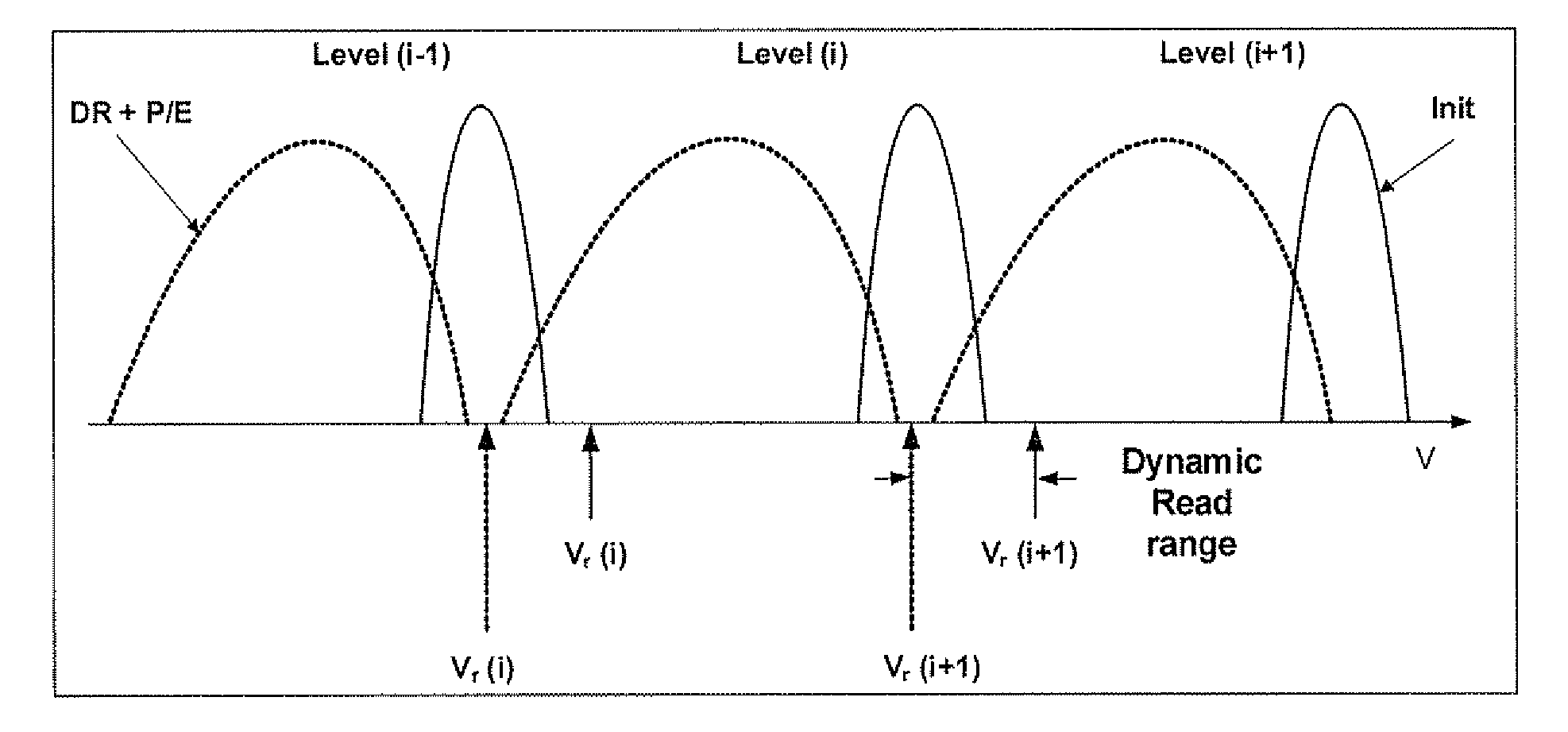
[0118]We performed simulations to evaluate the effectiveness of algorithm 2 and 3 using L=16 and several values for m.

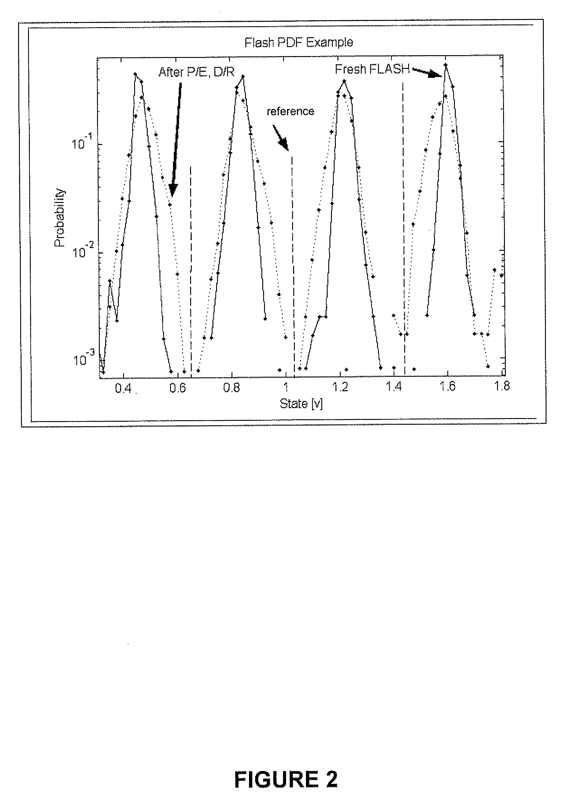
[0119]The simulations were performed using the following steps:[0120]We started with a multi-Gaussian CVD corresponding to initial (default) read voltage thresholds.[0121]With Δω=W / 64, for each of the Gaussians in the CVD we randomly chose a shift SH based on a normal distribution N(μSH=−1.07Δω,σSH=0.53Δω) and a widening factor WD based on a normal distribution N(μWD=0,σWD=0.21Δω) and changed the Gaussians parameters accordingly. In other words, the i-th Gaussian in the updated CVD is a Gaussian that initially had a distribution N(μi,σi), where σi=Δω and μi=iW / 16, and after the change had a distribution N((μf=μi+μSH,σf=√{square root over (σi2+σWD2+σSH2)}).[0122]We randomly generate a read page according to the updated CVD.[0123]We measure the CER according to the default read reference threshold voltages, denoted as CERdefault.[0124]We measure the CER according to th...


PUM


Abstract

Each of a plurality of flash memory cells is programmed to a respective one of L≧2 threshold voltage states within a threshold voltage window. Values of parameters of threshold voltage functions are adjusted in accordance with comparisons of the threshold voltages of some or all of the cells to two or more of m≧2 threshold voltage intervals within the threshold voltage window. Reference voltages for reading the cells are selected based on the values. Alternatively, the m threshold voltage intervals span the threshold voltage window, and respective threshold voltage states are assigned to the cells based on numbers of cells whose threshold voltages are in the intervals, without re-reading the cells.

Description

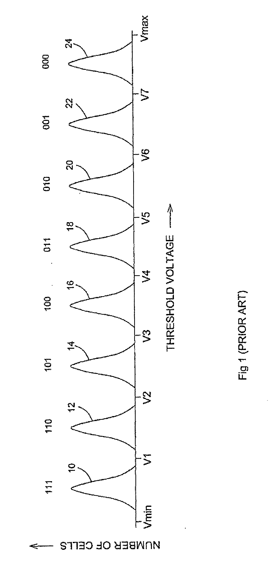
[0001]This patent application claims the benefit of U.S. Provisional Patent Application No. 60 / 913,299, filed Apr. 23, 2007FIELD AND BACKGROUND OF THE INVENTION[0002]The present invention relates to multi-bit-per-cell flash memories and, more particularly, to a method of optimizing read reference voltages for a multi-bit-per-cell flash memory.[0003]Originally, flash memories stored only one bit per cell. Flash memories that store two bits per cell now are available commercially, and flash memories that store more than two bits per cell are being developed. Conventionally, flash memories that store one bit per cell are called “Single Level Cell” (SLC) memories and flash memories that store more than one bit per cell are called “Multi Level Cell” (MLC) memories. This nomenclature is misleading because the cells of a SLC memory actually have two levels, for indicating whether the single bits stored therein are “1” bits or “0” bits. Therefore, these two kinds of flash memories are refer...

Claims


Application Information

Patent Timeline
Patent Type & Authority Applications(United States)
IPC IPC(8): G06F12/02G11C16/26G11C16/10
CPCG11C11/5628G11C11/5642G11C2211/5634G11C16/28G11C16/10G11C16/34G11C16/30G11C16/12
Inventor LITSYN, SIMONALROD, IDANSHARON, ERAN
Owner RAMOT AT TEL AVIV UNIV LTD
Learn More