
Multi-layer semiconductor structure and manufacturing method thereof

Inactive Publication Date: 2008-10-16
PROMOS TECH INC
View PDF1 Cites 3 Cited by
  • Summary
  • Abstract
  • Description
  • Claims
  • Application Information

AI Technical Summary

Benefits of technology

[0008]The present invention provides a multi-layer semiconductor structure and manufacturing method thereof, with a view to increasing device density, and providing various semiconductor structures to increase diversity of device design. Moreover, manufacturing scrap expense due to defects in wafer bonding can be avoided.

Problems solved by technology

However, as devices become closer, manufacture becomes more difficult and integration density is limited.
Moreover, some problems such as crosslink, timing delay and thermal effect may occur.
Wafer bonding has a problem of common interface defects; the majority of the interface defects are voids.
Interface defects may occur in the bonding process, during long-term storage, under heat treatment or in the wafer grinding process.
The defects occurring in bonding may be caused by residual particles, surface convexity, insufficient bonding filler or residual gases at the interface.
If the wafers are stored for a long time before bonding, or heat-treated after bonding, interface defects may be caused by reaction of bonding filler and substrate, damage to surface bonding, or contamination or peeling of bonding surface or interface.
Therefore, yield and reliability of devices are decreased.
Moreover, different glue conditions may generate bubbles on a glue interface and therefore decrease yield of the gluing process.
Excessive glue pressure may break wafers.
Also, wafers may break during heat treatment due to large differences between thermal expansion coefficients of bonding materials.
In view of the risks of wafer bonding and the formation of semiconductor structures on wafers needing to undergo more than one hundred processes, problems occurring during wafer bonding can nullify all previous efforts and lead to increases in manufacturing cost.

Method used


Image

  • Multi-layer semiconductor structure and manufacturing method thereof
  • Multi-layer semiconductor structure and manufacturing method thereof
  • Multi-layer semiconductor structure and manufacturing method thereof

Examples


Embodiment Construction

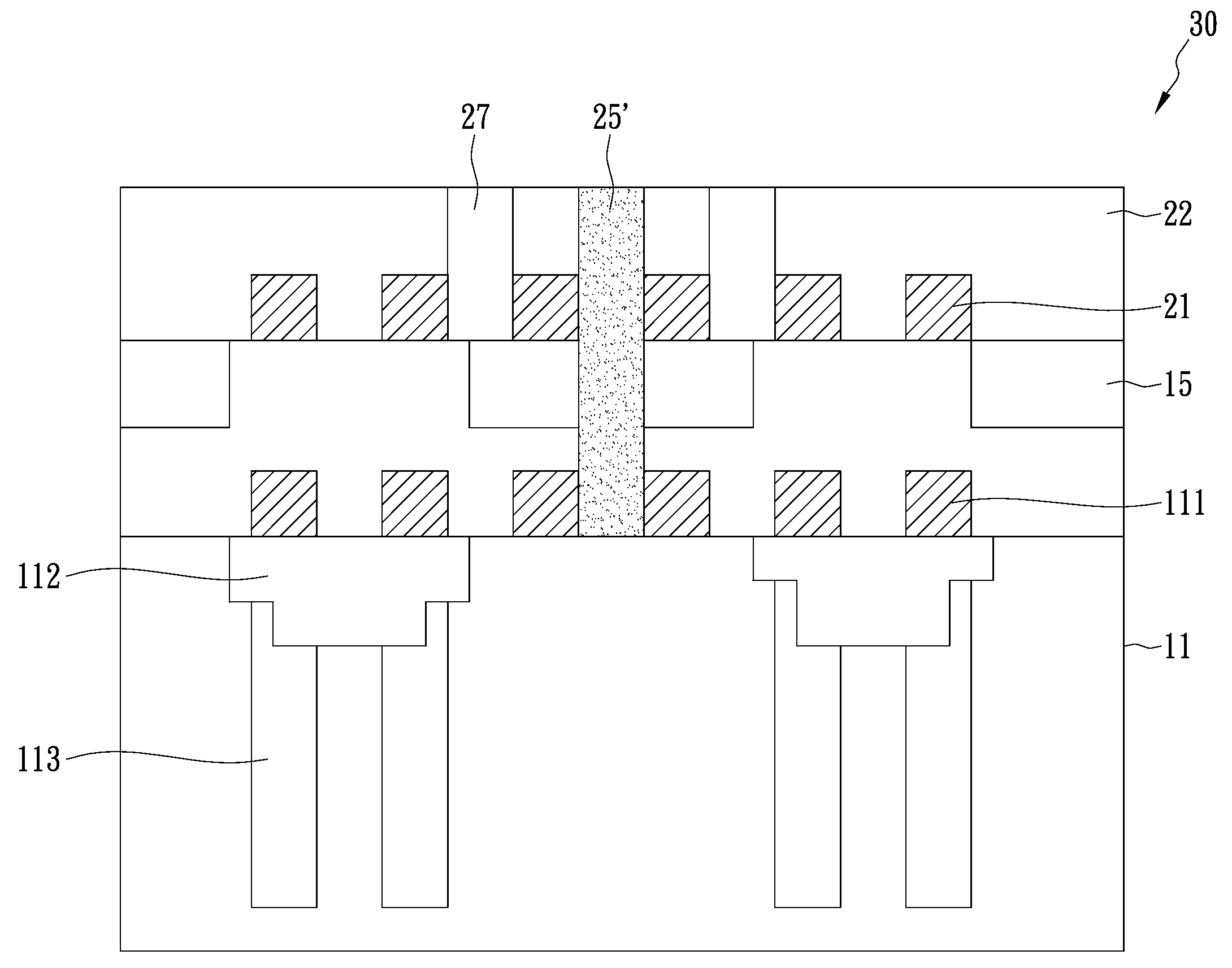
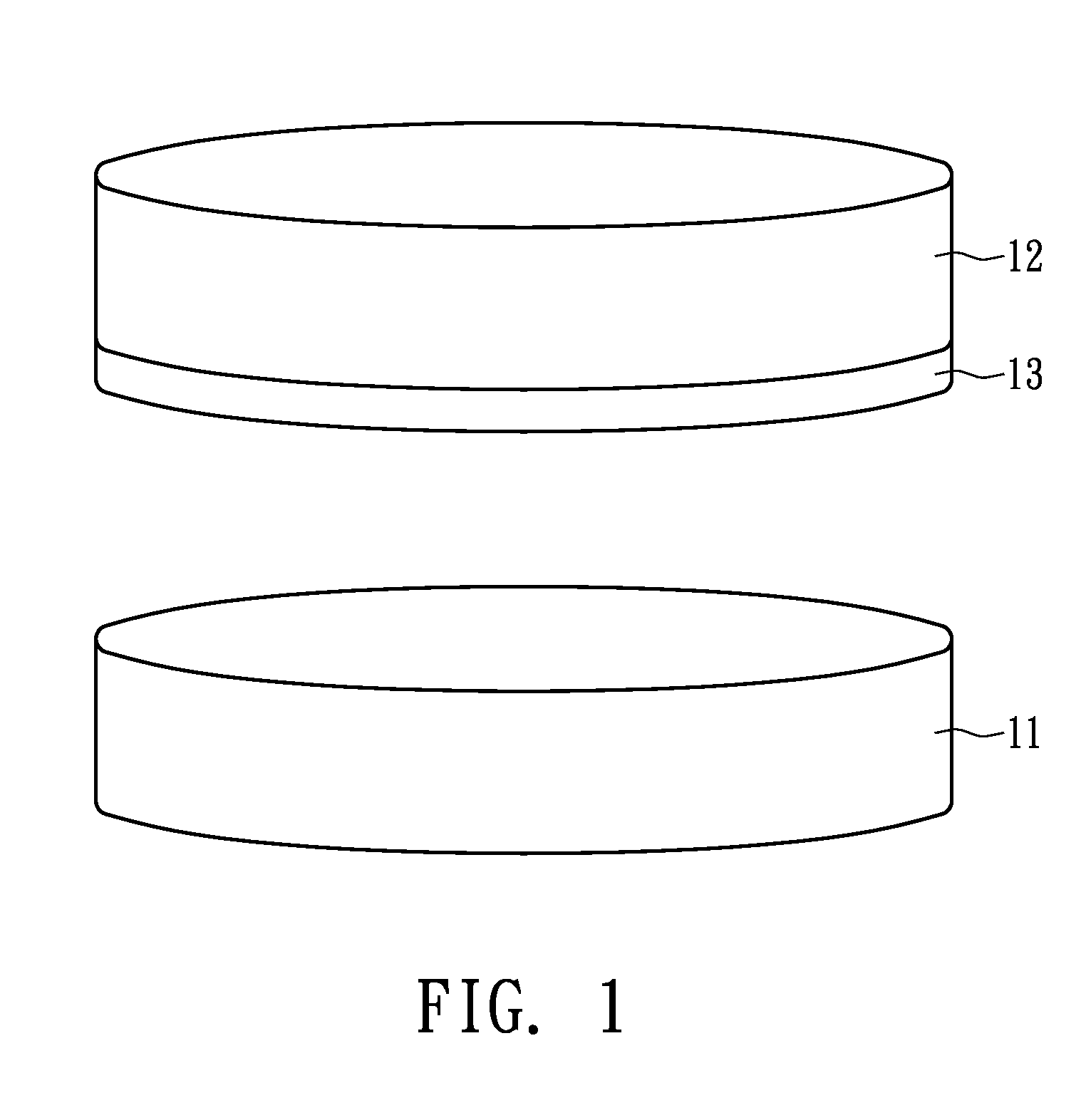
[0015]FIG. 1 illustrates the manufacturing method of a multi-layer semiconductor structure in accordance with the present invention, in which two wafers 11 and 12 are combined by wafer bonding technology. A glue layer 13 is between the wafers 11 and 12. The wafer 11 includes a fabricated semiconductor device structure, whereas the wafer 12 serves as a substrate for forming another semiconductor device structure. The two wafers 11 and 12 include either similar semiconductor device structures, e.g., DRAMs, or different semiconductor device structures, e.g., a logic device structure and a DRAM structure; or a memory circuit and a solar cell circuit, thereby providing diversity of combinations. The semiconductor device structures of the first and second wafers can be selected from the group consisting of DRAM structure of deep trench type, DRAM structure of stack type, logic device structure and flash memory structure.

[0016]Manufacture of a memory structure is exemplified as follows:

[00...


PUM


Abstract

A method for manufacturing a multi-layer semiconductor structure is disclosed. First, a first wafer comprising a first semiconductor device structure and a second wafer comprising a substrate and a single crystal silicon layer are provided, and the first and second wafers are combined in which a surface of the first wafer having the first semiconductor device structure is in contact with a surface of the second wafer having the single crystal silicon layer. A glue layer and a dielectric layer can be employed to combine the first and second wafers. Afterwards, a process for manufacturing a second semiconductor device structure is performed on the single crystal silicon layer.

Description

BACKGROUND OF THE INVENTION[0001](A) Field of the Invention[0002]The present invention relates to a semiconductor structure and manufacturing method thereof, and more specifically, to a multi-layer semiconductor structure and manufacturing method thereof using wafer-bonding technology[0003](B) Description of the Related Art[0004]With continuing improvements in semiconductor technology, line width gradually shrinks to increase integration density. However, as devices become closer, manufacture becomes more difficult and integration density is limited. Moreover, some problems such as crosslink, timing delay and thermal effect may occur.[0005]Consequently, a double-layer semiconductor structure in combination with two wafers is generated. In addition to increasing the density of devices, different semiconductor structures may be integrated for various applications. U.S. Pat. No. 6,423,613 discloses a process in which semiconductor structures are formed in two wafers first, and the two ...

Claims


Application Information

Patent Timeline
IPC IPC(8): H01L27/108H01L21/46
CPCH01L21/187H01L27/105H01L27/10844H01L27/10894H01L27/11517H10B12/01H10B12/09H10B41/00H10B12/0335
Inventor LEE, JACKLU, HERBERTLIU, MARVINPONG, PETER
Owner PROMOS TECH INC
Learn More