
Can bodymaker

a bodymaker and press technology, applied in the field of long stroke presses, can solve the problems of enormous and extremely expensive cupping presses, and achieve the effect of avoiding all the expense and bulk, and no scrappag

Active Publication Date: 2019-03-12
CROWN PACKAGING TECH
View PDF17 Cites 1 Cited by
  • Summary
  • Abstract
  • Description
  • Claims
  • Application Information

AI Technical Summary

Benefits of technology

[0007]The bodymaker of the invention thus avoids all the expense and bulk of a traditional free-standing cupper. By using pre-cut discs there is no scrappage resulting from in situ forming of discs on a cupping press.

Problems solved by technology

The cupping press is an enormous, and extremely expensive, machine.

Method used


Image

  • Can bodymaker
  • Can bodymaker
  • Can bodymaker

Examples


Embodiment Construction

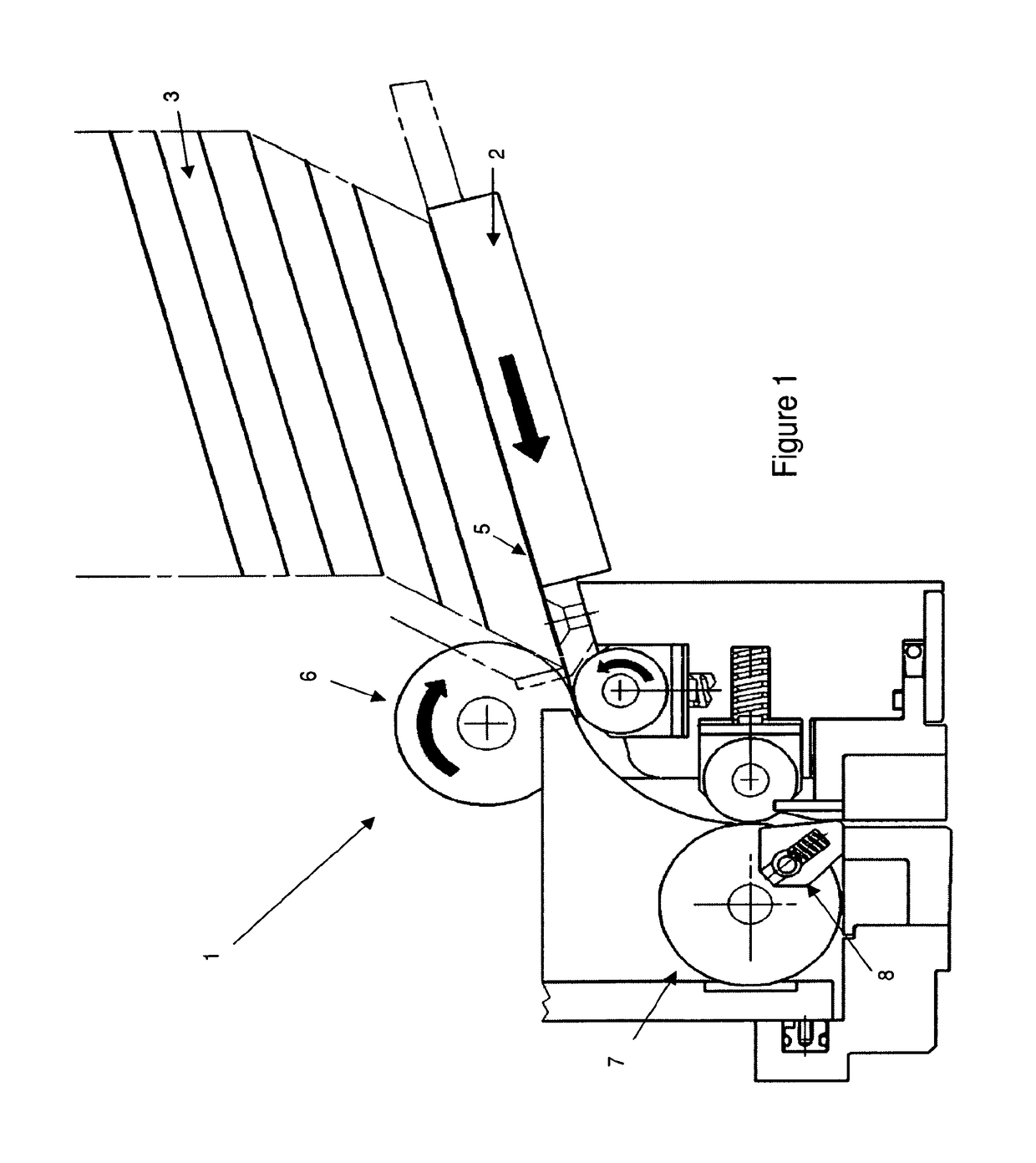
[0022]The embodiment of FIGS. 1 to 7 uses a roller feed arrangement 1 and feed plate slide 2. The discs are stacked in a hopper 3, which is located above the infeed sitting on a dead plate. Down the centre of the dead plate is a slot with a short stroke slide. The slide would have a recess or spring-loaded finger or pawl, which would protrude the thickness of the disc 5.

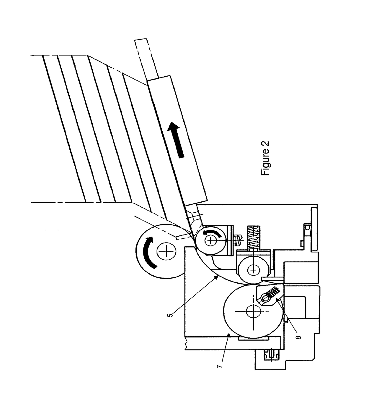
[0023]When the slide 2 moves forward it pushes the disc into the top set of rollers 6 which grip the disc 5 and drive it forward around the guide to the second set of rollers 7. The rollers 6, 7 move the disc 5 around a small curve and are easy to drive. The large rollers of the pairs are driven and dictate the disc speed. The small rollers are spring-loaded to supply the nip for gripping the disc. The small rollers maintain contact with the disc or drive roller to avoid skidding.

[0024]In FIG. 2, the second set of rollers 7 grips the disc 5 and drives it downwards into a locator 9 (FIG. 3) which positions the disc ce...


PUM

PropertyMeasurementUnit
sizeaaaaaaaaaa
thicknessaaaaaaaaaa
shapeaaaaaaaaaa

Abstract

A can bodymaker, which includes a disc feed (1) for feeding a disc (5) directly to the bodymaker itself. A locator (9) positions the disc (5) centrally to a blankholder (12) and a draw pad (10) clamps the disc (5) against a draw die (11). The blankholder (12) then forms the disc into a cup (20) and clamps the cup against a redraw die (14) ready to be picked up by a punch and carried through dies for forming a can body.

Description

TECHNICAL FIELD[0001]This invention relates to a long stroke press or, as it is known in the can making industry, a bodymaker, for drawing hollow articles such as metal containers or cans.BACKGROUND ART[0002]In known bodymakers for the production of thin-walled metal cans by the so-called “drawing and wall-ironing” (DWI) process, cups are fed to the bodymaker and carried by a punch on the end of the ram, through a series of ironing dies to obtain the desired size and thickness of the can. Ultimately, the can body carried on the punch may contact a bottom forming tool so as to form a shape such as a dome on the base of the can.[0003]The cup is mounted on the free end of a punch which extends from a reciprocating ram, and the cup wall is then “ironed” by passing through one or more ironing dies to lengthen the side wall of the cup and form a can.[0004]In existing apparatus for the formation of a “two piece” container (i.e. one piece can body with side wall and base, and separate end c...

Claims


Application Information

Patent Timeline
Patent Type & Authority Patents(United States)
IPC IPC(8): B21D22/00B21D22/28B21D43/00
CPCB21D22/00B21D43/00B21D22/28B21D37/18B21D43/12B21D51/2692
Inventor EGERTON, DANIELWOULDS, WILLIAM
Owner CROWN PACKAGING TECH
Learn More