
Circumvolve cutters for drill bit

a cutter and circular motion technology, applied in the field of drill bits, can solve the problems of reducing the service affecting the performance of the drill bit, and reducing the rate of damage, so as to improve the performance and operation life of the drill bit, and reduce the damage rate

Inactive Publication Date: 2008-10-16
GEN ELECTRIC CAPITAL
View PDF19 Cites 36 Cited by
  • Summary
  • Abstract
  • Description
  • Claims
  • Application Information

AI Technical Summary

Benefits of technology

[0005]In view of the foregoing and other considerations, the present invention relates to methods and apparatus for improving drill bit performance and operational life by reducing the rate of damage caused by impact, thermal degradation and abrasive wear.
[0008]In another embodiment, the method includes the steps of providing a drill bit comprising a cutter assembly, wherein the cutter assembly comprises a planar table and a dampening mechanism, disposing the drill bit in a well bore adjacent to a formation, rotating the drill bit around a bit axis, engaging a portion of the planar table to the formation to cut a portion of the formation, and dampening at least a portion of the impact on the drill bit as the drill bit engages the formation.

Problems solved by technology

Oftentimes, these cutters become dull and require replacement, which limits the rate of penetration into the rock as well as footage drilled.
The cutters may be damaged by impact, thermal degradation and abrasive wear, factors which significantly reduces the life of the cutting elements.
For example, while polycrystalline diamond compact (PDC) bits are effective when drilling in soft formations, the PDC bits' performance has been limited while drilling in hard-rock and abrasive formations due to impact damage and wear.
However, these methods do not take into consideration the instability of the drill string.

Method used


Image

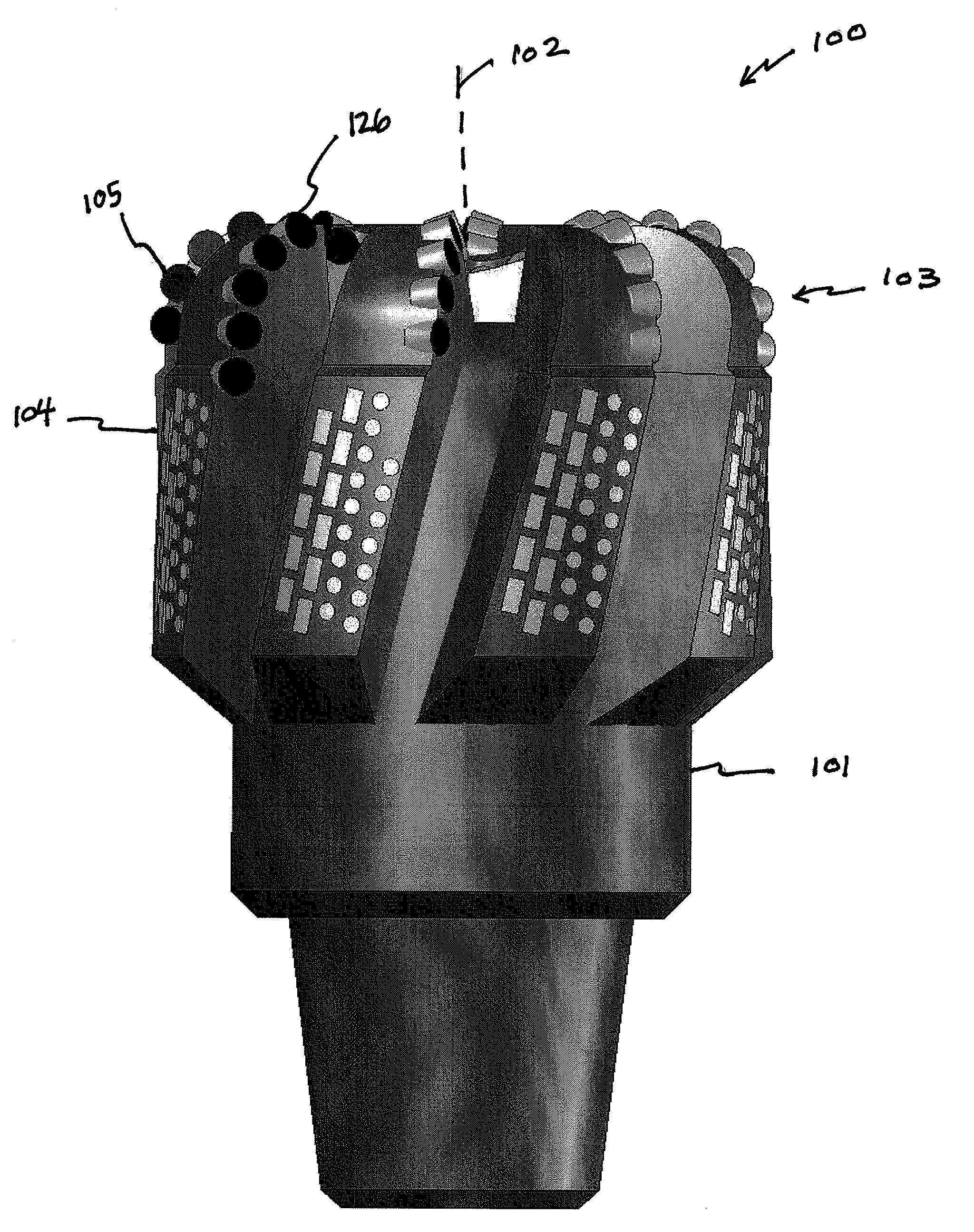
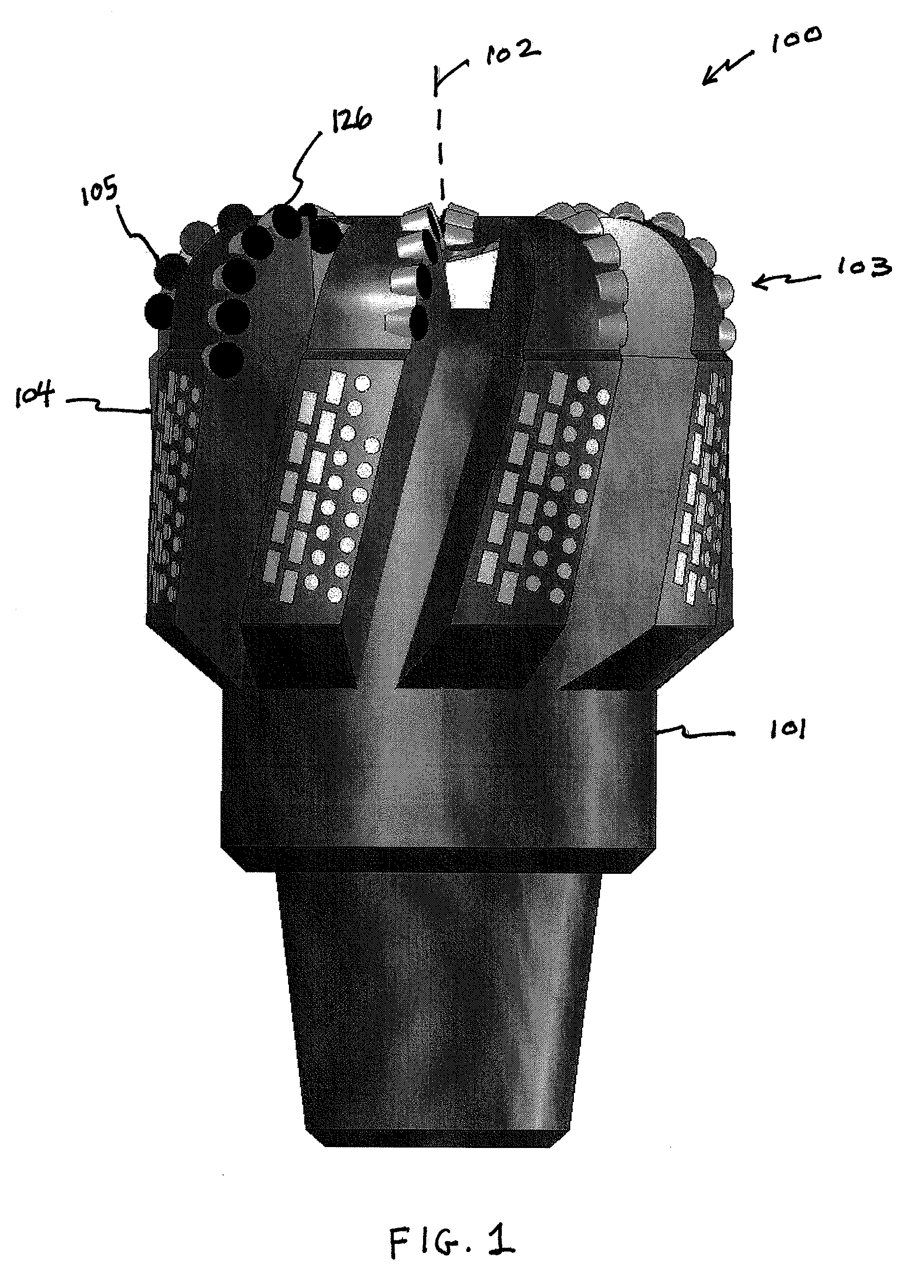
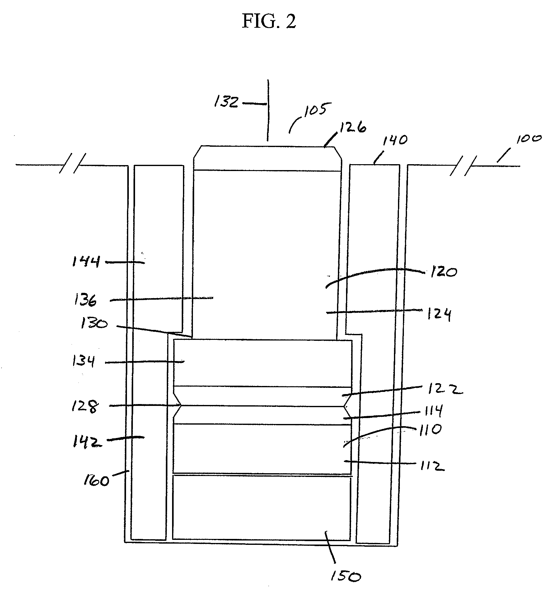
  • Circumvolve cutters for drill bit
  • Circumvolve cutters for drill bit
  • Circumvolve cutters for drill bit

Examples


Embodiment Construction

[0016]The following discussion is presented to enable a person skilled in the art to make and use the invention. The general principles described herein may be applied to embodiments and applications other than those detailed below without departing from the spirit and scope of the present invention as defined by the appended claims. The present invention is not intended to be limited to the embodiments shown, but is to be accorded the widest scope consistent with the principles and features disclosed herein.

[0017]As such, those skilled in the art will appreciate that the conception, upon which this disclosure is based, may readily be utilized as a basis for the designing of other structures, methods, and devices for carrying out the several purposes of the present invention. It is important, therefore, that the claims be regarded as including such equivalent constructions insofar as they do not depart from the spirit and scope of the present invention.

[0018]FIG. 1 shows a perspecti...


PUM


Abstract

A drill bit comprising a cutter assembly, further comprising a planar table and a cutter substrate coupled to the planar table, wherein the cutter substrate has a cutter body axis and wherein the planar table is operable to rotate about the cutter body axis. The planar table may be exposed to the rock formation for cutting purposes but may rotate to reduce the time that any specific portion of the cutting edge is exposed to the formation to extend the life of the planar table, among other benefits.

Description

FIELD OF THE INVENTION[0001]The present invention relates generally to drilling tools and more particularly to drill bits.BACKGROUND[0002]Cutters are often utilized in drill bits for shearing through rock formations. Oftentimes, these cutters become dull and require replacement, which limits the rate of penetration into the rock as well as footage drilled. The cutters may be damaged by impact, thermal degradation and abrasive wear, factors which significantly reduces the life of the cutting elements. For example, while polycrystalline diamond compact (PDC) bits are effective when drilling in soft formations, the PDC bits' performance has been limited while drilling in hard-rock and abrasive formations due to impact damage and wear.[0003]The current trend in the industry is to force, vector, dynamic and energy balance PDC drill bits for stability purposes. However, these methods do not take into consideration the instability of the drill string. The drill string can have a dramatic e...

Claims


Application Information

Patent Timeline
IPC IPC(8): E21B7/00
CPCE21B10/573E21B10/62
Inventor MUMMA, MATTHEW D.SCHMIDT, JONATHAN R.JAMES, RANDY H.
Owner GEN ELECTRIC CAPITAL
Learn More