
Method and apparatus for improving the performance of suction powered pool cleaning systems

a technology of pool cleaning and suction power, which is applied in the direction of swimming pools, chemistry apparatus and processes, water/sludge/sewage treatment, etc., can solve the problems of increasing the likelihood of cavitation, increasing the magnitude of negative pressure, and insufficient water flow from the cleaner alone to satisfy the pump flow requirements. , to achieve the effect of reducing preventing cavitation, and increasing the capacity of pump flow

Inactive Publication Date: 2008-10-16
HENKIN LABY
View PDF10 Cites 21 Cited by
  • Summary
  • Abstract
  • Description
  • Claims
  • Application Information

AI Technical Summary

Benefits of technology

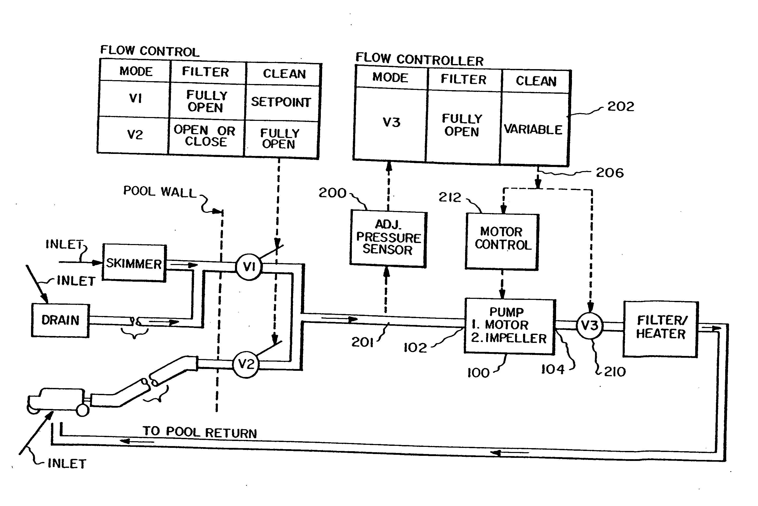
[0009]The present invention is directed to an automatic swimming pool cleaning system including a subsystem responsive to the magnitude of negative pressure at the pump suction inlet for controlling pump flow in order to prevent pump cavitation and / or create a constant high negative pressure at the pool wall for powering a pool cleaner. Systems in accordance with the invention are configured to pump a high rated volume of water when operating in a filtering mode and to provide a high negative pressure at the pool wall for powering the pool cleaner when operating in a cleaning mode. More particularly, embodiments of the invention are configured to provide a pressure at the pool wall more negative than −12″ Hg for powering a pool cleaner. This increase in available negative pressure, as contrasted with the prior art, permits the design of higher performance cleaners.
[0011]A first subsystem in accordance with the invention for preventing cavitation includes a pressure sensor for monitoring the negative pressure at, or just upstream from, the pump suction inlet. If the monitored pressured is more negative than a lower setpoint SL (e.g., −25″ Hg), the pump flow producing capability is reduced by closing a throttling valve downstream from the pump outlet to prevent the inlet pressure from falling to a level which could cause cavitation. If the monitored pressure is less negative (i.e., more positive) than an upper setpoint SU (e.g., −24″ Hg), the pump flow producing capability is increased by opening the downstream throttling valve. Thus, the subsystem operates in the cleaning mode to maintain the minimum pump inlet pressure at about −25″ Hg, thus preventing cavitation.

Problems solved by technology

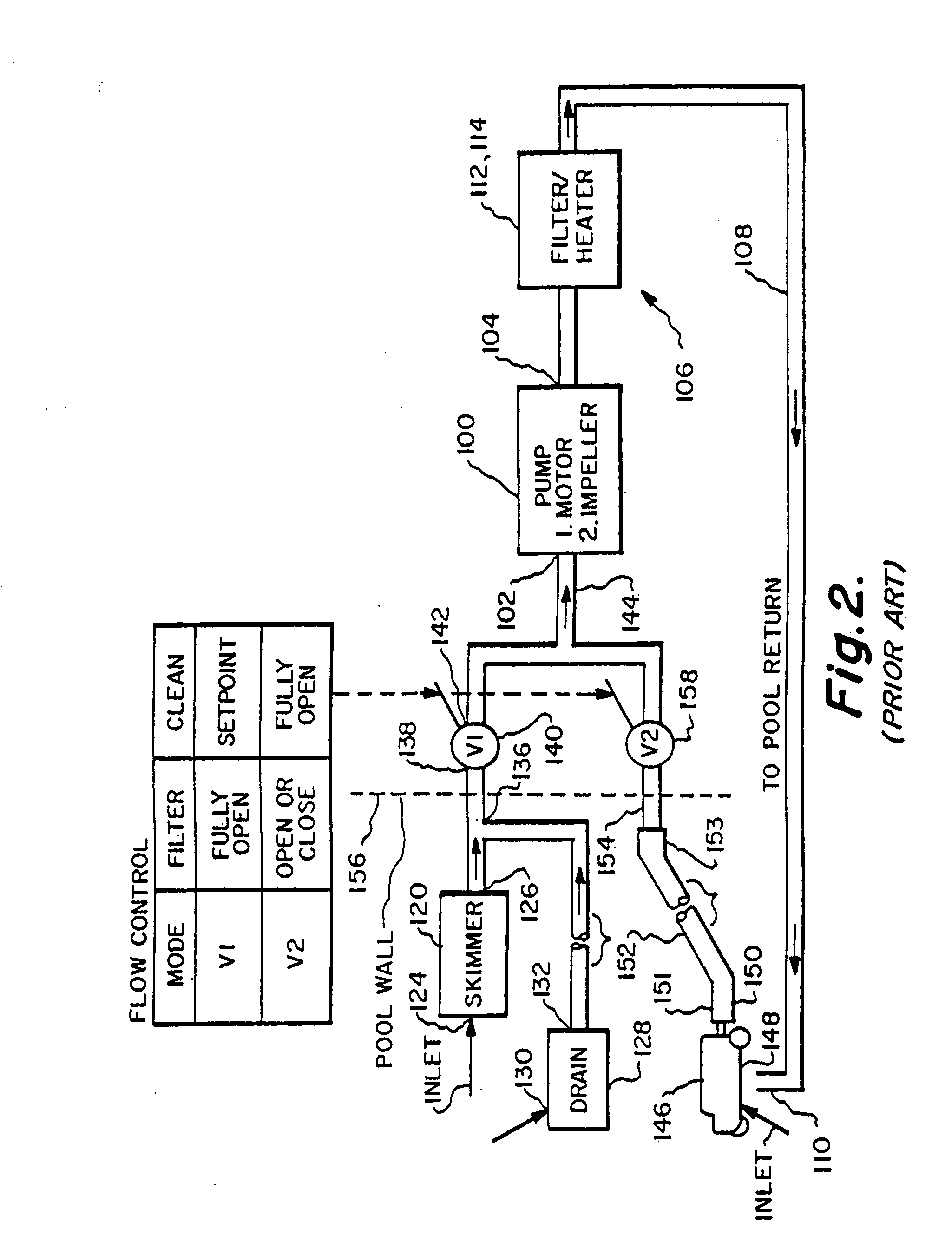
In typical existing systems, the water flow from the cleaner alone is frequently insufficient to satisfy pump flow requirements.
If a larger pump were selected, the likelihood of cavitation increases.
Thus, the magnitude of negative pressure (i.e., −12″ Hg) available at the pool wall for powering the cleaner is limited and has been a barrier to the design of higher performance cleaners.

Method used


Image

  • Method and apparatus for improving the performance of suction powered pool cleaning systems
  • Method and apparatus for improving the performance of suction powered pool cleaning systems
  • Method and apparatus for improving the performance of suction powered pool cleaning systems

Examples


Embodiment Construction

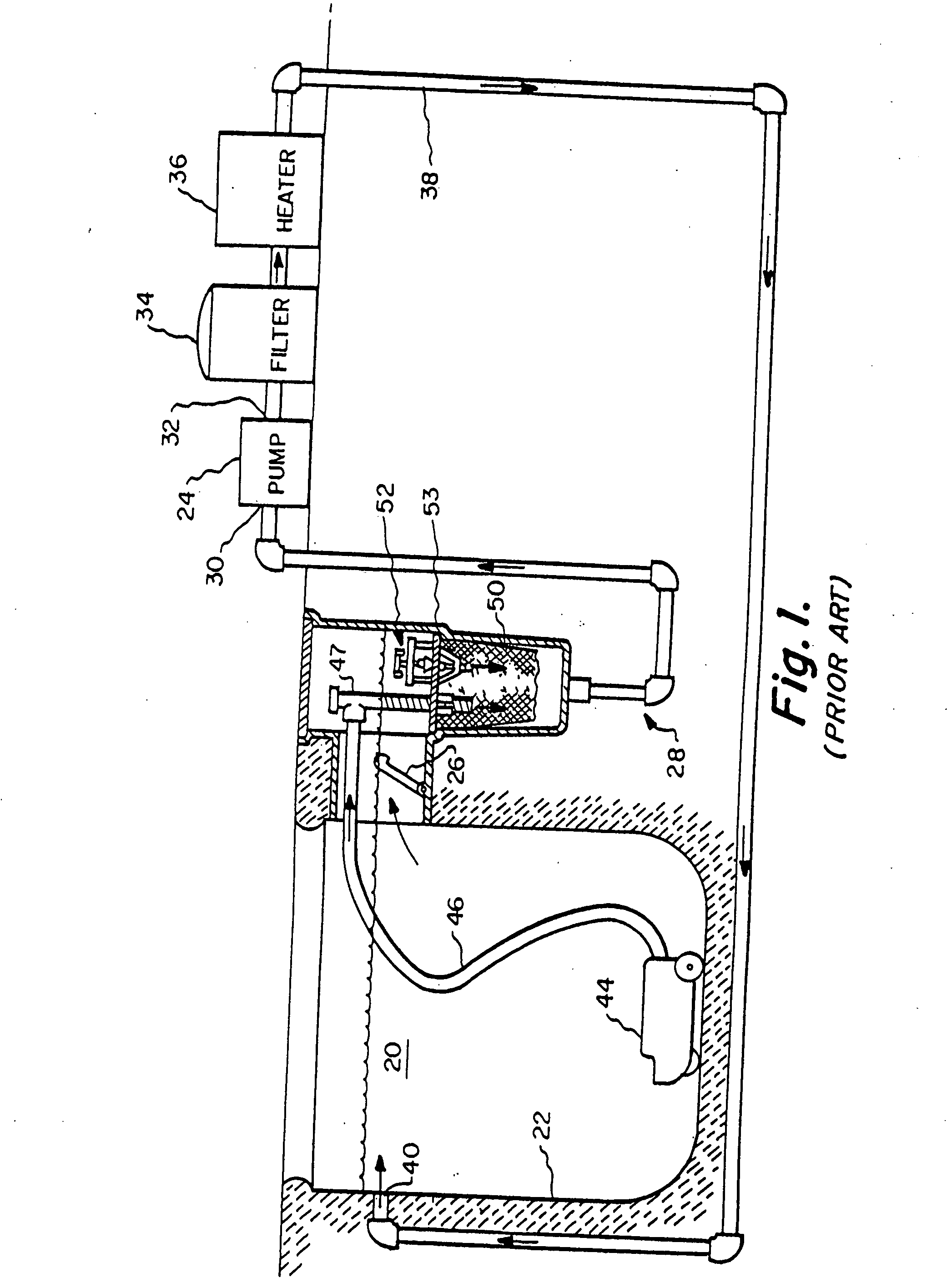
[0020]Attention is initially directed to FIG. 1 which diagrammatically depicts an exemplary conventional system for cleaning the water in pool 20 (i.e., filtering mode) as well as cleaning the surface of wall 22 (including bottom and side portions) containing the pool (i.e., cleaning mode). Water cleaning, i.e., filtering, is accomplished primarily by causing pump 24 to pull pool water 20 through skimmer and or drain 26 (“skimmer / drain”) through suction side plumbing 28 to the pump suction inlet 30. The pump pressure outlet 32 returns the water to the pool via a filter 34, and optionally a heater 36 and / or chlorinater via pressure side plumbing 38 to one or more return outlets 40.

[0021]Wall cleaning is primarily achieved by operating an automatic traveling pool cleaner 44 which is coupled via a flexible suction hose 46 and plumbing 28 to the pump suction inlet 30. The suction, i.e., negative pressure, provided by the pump 24 to the cleaner 44, powers the cleaner primarily to (1) pro...


PUM


Abstract

A pool cleaning system including means responsive to the magnitude of negative pressure at the suction inlet of a system pump for controlling pump water flow in order to prevent pump cavitation. Systems in accordance with the invention are configured to pump a high rated volume of water when operating in a filtering mode and to provide a high negative pressure to power a pool cleaner when operating in a cleaning mode.

Description

RELATED INVENTIONS[0001]This application is a continuation of PCT2006 / 027495 filed 13 Jul. 2006 which claims priority based on U.S. Application 60 / 705,080 filed 8 Feb. 2005. This application claims priority based on the aforementioned applications.FIELD OF THE INVENTION[0002]This invention relates generally to a swimming pool cleaning system utilizing an electrically driven pump for powering (1) a pool water filtration system and (2) an automatic pool cleaner; and more particularly to system improvements for preventing pump cavitation and for increasing the negative operating pressure (i.e., suction) available for powering the pool cleaner.BACKGROUND OF THE INVENTION[0003]Typical pool cleaning systems include an electrically driven pump which draws pool water into its suction inlet and discharges the water from its pressure outlet. The pool water drawn into the pump inlet is most typically captured by a pool skimmer and / or drain. The pool water discharged from the pump outlet is typ...

Claims


Application Information

Patent Timeline
IPC IPC(8): E04H4/16
CPCE04H4/1654E04H4/1672E04H4/1645
Inventor HENKIN, MELVYN L.LABY, JORDAN M.
Owner HENKIN LABY
Learn More