
Fingerprint Imaging System

a fingerprint imaging and fingerprint technology, applied in the field of fingerprint imaging systems, can solve the problems of external hoods or covers, and the performance of conventional systems may be degraded, so as to reduce the impact of ambient light on performance, and reduce the impact of ambient ligh

Active Publication Date: 2008-10-09
IDENTIFICATION INT
View PDF37 Cites 13 Cited by
  • Summary
  • Abstract
  • Description
  • Claims
  • Application Information

AI Technical Summary

Benefits of technology

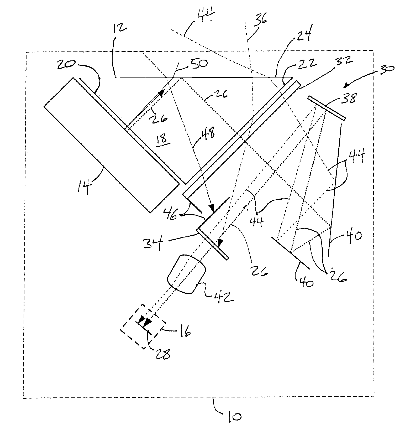
[0003]One aspect of the invention relates to a fingerprint imaging system. The fingerprint imaging system may be configured to capture an image of a friction ridge pattern of a subject (e.g., a fingerprint, a palm print, a hand print, a footprint, etc.). The system may include one or more components that reduce the impact of ambient light on the performance of the system. In some implementations, the system may reduce the impact of ambient light without requiring additional power (e.g., to generate an increased amount of radiation) and without including “external” hoods and / or covers designed to block ambient light prior to the ambient light entering system. Instead, the system may reduce the impact of ambient light on performance by blocking ambient light internally within the system along an optical path of radiation used to electronically capture an image of the friction ridge pattern.
[0006]The optical analyzer may include one or more optical elements configured to transmit only radiation with a requisite polarization. The optical analyzer may be disposed within the system between the platen and the image capture device to shield the image capture device from substantially all of the radiation within the system that does not have the requisite polarization. The optical analyzer may be formed such that the requisite polarization is different than the uniform polarization that is imparted to radiation by the polarizer 32. This may effectively screen the image capture device from at least some of the ambient light that enters the system through the platen. For example, a beam of ambient light entering the system to become incident on the polarizer and then on the optical analyzer would be polarized by the polarizer and blocked from reaching the image capture device by the optical analyzer, as the polarization imparted to the beam of ambient light by the polarizer would be different than the requisite polarization.
[0011]The arrangement of the linear polarizer and the quarter-wave retarder in the radiation emission module may reduce the impact of ambient light that enters the system through the platen and is reflected from the source back to the platen. For example, as a beam of ambient light enters the system through the platen and proceeds toward the source, the beam of ambient may become incident on the linear polarizer, which linearly polarizes the ambient light in a first orientation. The linearly polarized ambient light may then become incident on the quarter-wave retarder, which alters the polarization state of ambient light to make the ambient light circularly polarized. After being reflected by the source, the ambient light may then again become incident on the quarter-wave retarder, which may again change the polarization state of the ambient light to linear. However, the orientation of the polarization of ambient light after passing through the quarter-wave retarder a second time may be orthogonal to the orientation of linear polarization provided to the ambient light by the linear polarizer. Thus, as the ambient light becomes incident again on the linear polarizer, the polarization of the ambient light may be orthogonal to the polarization of the linear polarizer, which may thereby block ambient light by virtue of this orthogonality.

Problems solved by technology

However, the performance of conventional systems may be degraded by ambient light that is introduced to the systems during operation.
For example, a high-powered light source may negatively impact the power budget of the system.
External hoods or covers may increase the size and / or weight of the system, and may require additional parts that must be transported in conjunction with the system.
The radiation may be totally internally reflected at the platen, with the exception of the locations on the platen where the friction ridge pattern engages the platen, as total internal reflection may be frustrated at these locations.
In other words, the arrangement of the polarizer, the analyzer, and the polarization member may not be effective in blocking this beam of reflected ambient light because of the proximity (or even collocation) of the path of this beam with radiation emitted by the radiation emission module.

Method used


Image

  • Fingerprint Imaging System
  • Fingerprint Imaging System
  • Fingerprint Imaging System

Examples


Embodiment Construction

[0016]FIG. 1 illustrates a fingerprint imaging system 10, in accordance with one or more embodiments of the invention. System 10 may be configured to capture an image of a friction ridge pattern of a subject (e.g., a fingerprint, a palm print, a hand print, a footprint, etc.). System 10 may include one or more components that reduce the impact of ambient light on system 10. As is discussed further below, system 10 may reduce the impact of ambient light without requiring additional power (e.g., to generate an increased amount of radiation) or including “external” hoods and / or covers designed to block ambient light prior to the ambient light entering system 10. In some embodiments, system 10 includes a platen 12, a radiation emission module 14, an image capture device 16 and / or other components.

[0017]Platen 12 may be configured to engage the friction ridge pattern of the subject. In some embodiments, platen 12 may be provided by a prism 18. Prism 18 may be formed such that radiation i...


PUM


Abstract

A fingerprint imaging system configured to capture an image of a friction ridge pattern of a subject (e.g., a fingerprint, a palm print, a hand print, a footprint, etc.). The system may include one or more components that reduce the impact of ambient light on the performance of the system. In some implementations, the system may reduce the impact of ambient light without requiring additional power (e.g., to generate an increased amount of radiation) and without including “external” hoods and / or covers designed to block ambient light prior to the ambient light entering system. Instead, the system may reduce the impact of ambient light on performance by blocking ambient light internally within the system along an optical path of radiation used to electronically capture an image of the friction ridge pattern.

Description

FIELD OF THE INVENTION[0001]The invention relates to the reduction of ambient light within a fingerprint imaging system configured to electronically capture an image of a friction ridge pattern of an individual.BACKGROUND OF THE INVENTION[0002]Fingerprint imaging systems that electronically capture images of friction ridge patterns of individuals are known. However, the performance of conventional systems may be degraded by ambient light that is introduced to the systems during operation. For example, ambient light may saturate images of the friction ridge in a conventional system. Typically, to address this issue, a fingerprint imaging system may include a relatively high-powered light source to overcome the problem of saturation, and / or external hoods or covers that block ambient light before it enters the system. Each of these solutions is associated with its own drawbacks. For example, a high-powered light source may negatively impact the power budget of the system. External hoo...

Claims


Application Information

Patent Timeline
IPC IPC(8): G06K9/74
CPCG06K9/00046G06V40/1324
Inventor FENRICH, RICHARD KARLLI, LIN
Owner IDENTIFICATION INT
Learn More