
System and method for processing video images for camera recreation

a video image and camera technology, applied in the field of processing graphical images, can solve problems such as distortion of objects stretched ou

Inactive Publication Date: 2008-10-09
CONVERSION WORKS
View PDF27 Cites 46 Cited by
  • Summary
  • Abstract
  • Description
  • Claims
  • Application Information

AI Technical Summary

Problems solved by technology

Specifically, the stretching operations cause distortion of the object being stretched.

Method used


Image

  • System and method for processing video images for camera recreation
  • System and method for processing video images for camera recreation
  • System and method for processing video images for camera recreation

Examples


Embodiment Construction

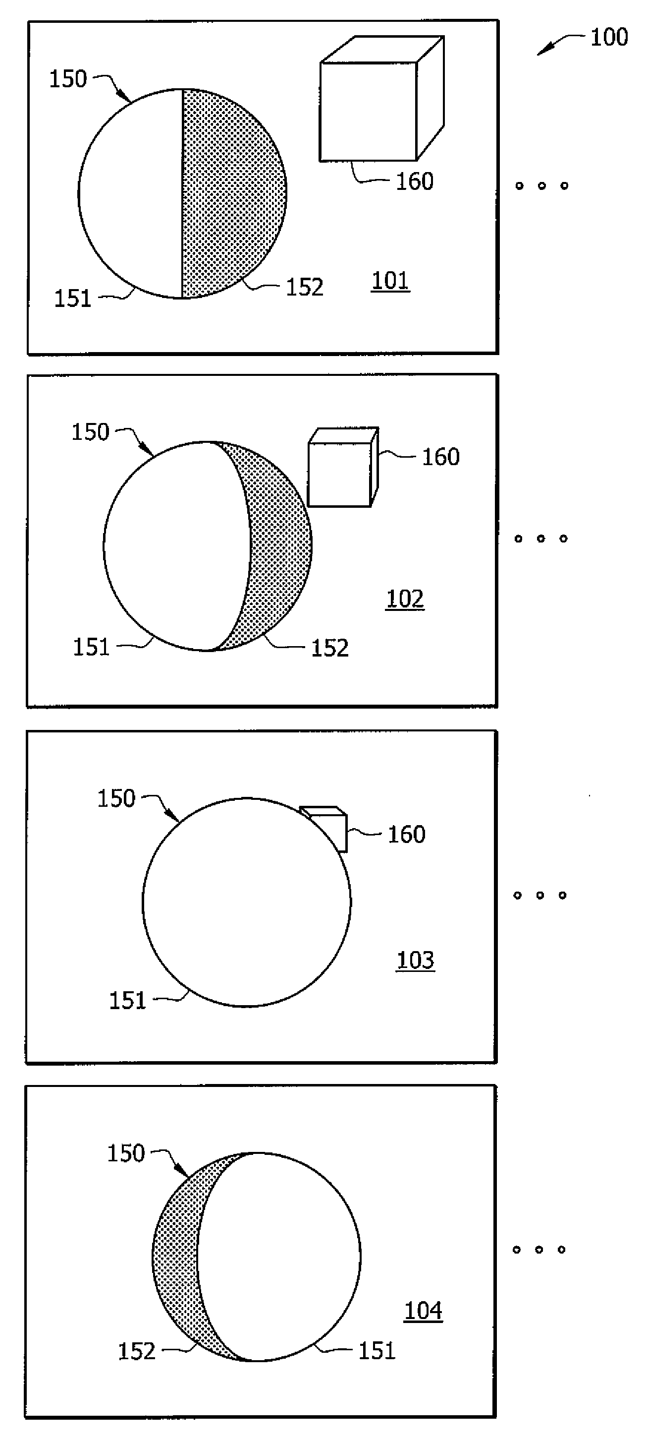
[0026]Referring now to the drawings, FIG. 1 depicts sequence 100 of video images that may be processed according to some representative embodiments. Sequence 100 of video images includes key frames 101-104. Multiple other frames may exist between these key frames.

[0027]As shown in FIG. 1, sphere 150 possesses multiple tones and / or chromatic content. One half of sphere 150 is rendered using first tone 151 and the other half of sphere 150 is rendered using second tone 152. Sphere 150 undergoes rotational transforms through video sequence 100. Accordingly, in key frame 102, a greater amount of tone 151 is seen relative to key frame 101. In key frame 103, sufficient rotation has occurred to cause only tone 151 of sphere 150 to be visible. In key frame 104, tone 152 becomes visible again on the opposite side of sphere 150 as compared to the position of tone 152 in key frame 101.

[0028]Box 160 is subjected to scaling transformations in video sequence 100. Specifically, box 160 becomes smal...


PUM


Abstract

Embodiments use point clouds to recreate a camera. The point cloud of the object may be formed from analysis of two dimensional images taken by the camera. Once the virtual camera has been formed, the camera may be used in the process of generating stereoscopic three dimensional images of the scene within the 2D images.

Description

CROSS-REFERENCE TO RELATED APPLICATIONS[0001]The present application is a continuation-in-part of U.S. patent application Ser. No. 10 / 946,955, entitled “SYSTEM AND METHOD FOR PROCESSING VIDEO IMAGES”, filed Sep. 22, 2004 and published as US 2006 / 0061583 on Mar. 23, 2006, the disclosure of which is hereby incorporated by reference.[0002]The present application claims priority to U.S. provisional patent application No. 60 / 894,450, entitled “TWO-DIMENSIONAL TO THREE-DIMENSIONAL CONVERSION”, filed Mar. 12, 2007, the disclosure of which is hereby incorporated by reference.[0003]The present application is related to U.S. patent application Ser. No. 11 / 627,414, entitled “METHODOLOGY FOR 3D SCENE RECONSTRUCTION FROM 2D IMAGE SEQUENCES”, filed Jan. 26, 2007, U.S. patent application Ser. No. (______ [Attorney Docket No. 69126-P010US-10712474]), entitled SYSTEMS AND METHODS FOR GENERATING 3-D GEOMETRY USING POINTS FROM IMAGE SEQUENCES, filed concurrently herewith, and U.S. patent application S...

Claims


Application Information

Patent Timeline
IPC IPC(8): H04N13/02H04N13/221
CPCG06T7/004G06T15/20G06T15/205G06T2207/30244H04N13/0221H04N13/026H04N13/0275H04N13/0289G06T7/70H04N13/289H04N13/221H04N13/275H04N13/261
Inventor LOWE, DANNY D.SPOONER, DAVID A.KEECH, GREGORY R.SIMMONS, CHRISTOPHER L.WALLNER, NATASCHABIRTWISTLE, STEVENADELMAN, JONATHAN
Owner CONVERSION WORKS
Learn More