Method of coating sulfide phosphor and light emitting device employing coated sulfide phosphor

a technology of thiogallate phosphor and light-emitting device, which is applied in the direction of discharge tube luminescnet screen, natural mineral layered product, coating, etc., can solve the problem of inability to achieve approximately natural color, difficulty in achieving color-rendering index, and initial optical properties of thiogallate phosphor tend to deteriorate quickly

Inactive Publication Date: 2008-10-02
SEOUL SEMICONDUCTOR
View PDF23 Cites 42 Cited by
  • Summary
  • Abstract
  • Description
  • Claims
  • Application Information

AI Technical Summary

Problems solved by technology

However, a white LED obtained by the combination of the blue LED and the yellow phosphors has difficulty in achieving a color-rendering index of 85 or more, and cannot realize approximately natural color due to low color purity after light penetrates a color filter when used as a backlight source for a Liquid Crystal Display (LCD).
However, since sulfide-based thiogallate phosphors such as (Ca,Sr,Ba)(Al,In,Ga)2S4:Eu phosphors have poor chemical stability with respect to moisture, the initial optical properties of thiogallate phosphors tend to deteriorate quickly.
As such, since the nitride phosphor-based white light emitting device provides light exhibiting lower color purity after penetrating the color filter, there is a difficulty in applying the nitride phosphor-based white light emitting device to the backlight source for the LCD.
However, since the sulfide-based phosphor has a very low stability with respect to moisture, it is difficult to apply the sulfide-based phosphor to the light emitting device.
In particular, (Ca,Sr,Ba)(Al,In,Ga)2S4:Eu phosphors and (Ca,Sr)S:Eu phosphors react with moisture and are converted to carbonates or sulfates, finally resulting in failure of their inherent luminescence properties.
However, even when coated with the silicon oxide film, the sulfide phosphor does not have sufficient moisture stability.
If the titanium oxide precursor is mixed in a ratio less than 5 wt %, the sulfide phosphor fails to have improved chemical stability with respect to moisture.
If the zinc oxide precursor is mixed in a ratio less than 5 wt %, the sulfide phosphor fails to have improved chemical stability with respect to moisture.

Method used


Image

  • Method of coating sulfide phosphor and light emitting device employing coated sulfide phosphor
  • Method of coating sulfide phosphor and light emitting device employing coated sulfide phosphor
  • Method of coating sulfide phosphor and light emitting device employing coated sulfide phosphor

Examples


example 1

[0055]TEOS was used as a silicon oxide precursor and boron triethoxide was used as a boron oxide precursor. TEOS was diluted in a ratio of 1 wt % (with respect to the weight of phosphor) per 1 cc of anhydrous ethanol, and boron triethoxide was diluted in a ratio of 0.25 wt % (with respect to the weight of phosphor) per 1 cc of anhydrous ethanol.

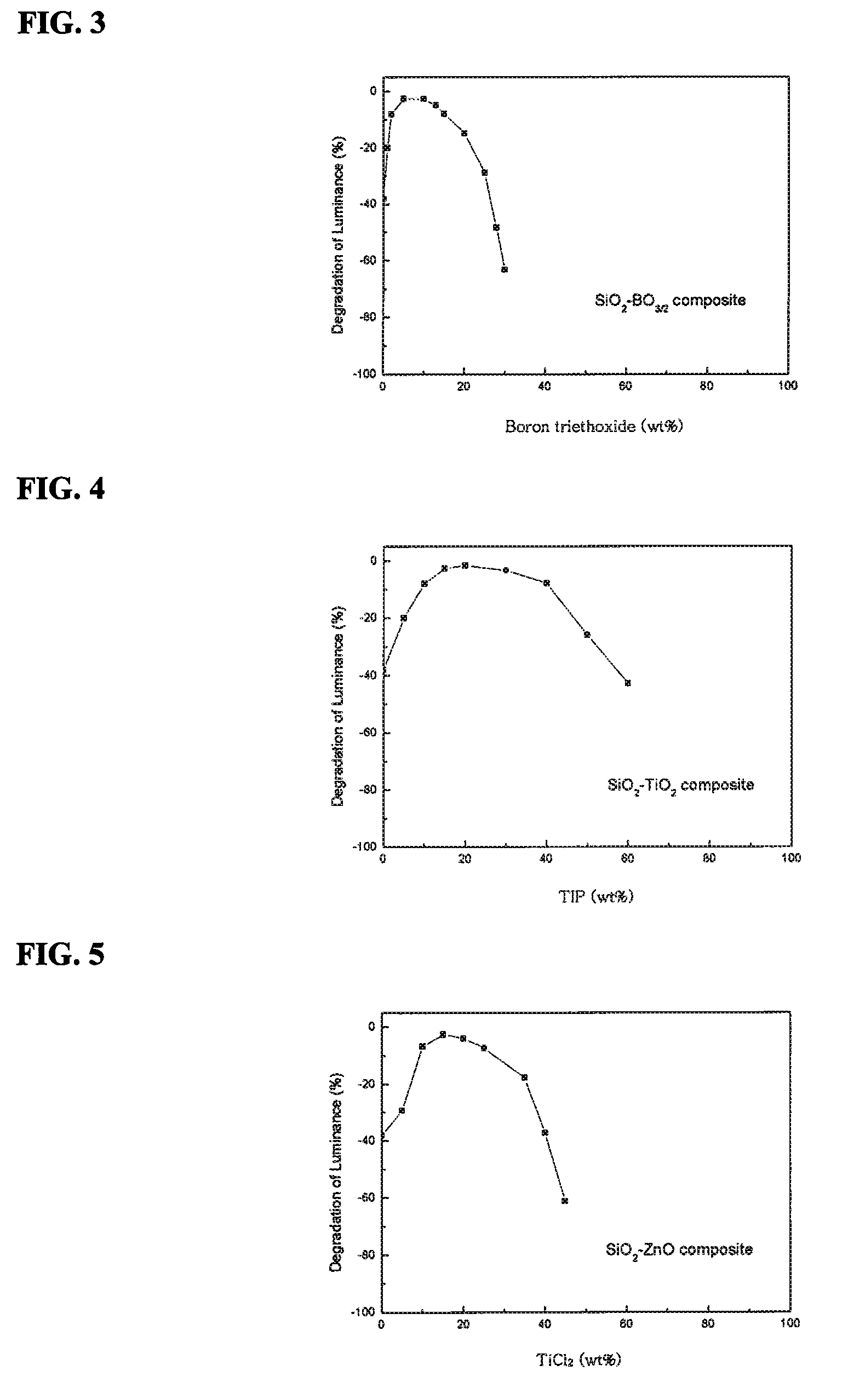
[0056]A total weight ratio of the TEOS and boron triethoxide precursors was fixed to 3 wt % with respect to the weight of (Ca, Sr)S:Eu phosphor. An oxide layer was formed on the surface of 3 g of sulfide phosphor by changing a weight ratio of the boron triethoxide precursor with respect to the total weight of the precursors while maintaining other conditions. Then, moisture stability of the phosphor coated with the oxide layer was tested.

[0057]To determine a relationship between the moisture stability of the sulfide phosphor and the weight ratio of the boron triethoxide precursor, after exposing the phosphor to 100° C. steam for 10 hours, lum...

example 2

[0059]TEOS was used as a silicon oxide precursor and TIP was used as a titanium oxide precursor. Both TEOS and TIP were diluted in a ratio of 1 wt % (with respect to the weight of phosphor) per 1 cc of anhydrous ethanol.

[0060]A total weight ratio of TEOS and TIP was fixed to 3 wt % with respect to the weight of (Ca, Sr)S:Eu phosphor. An oxide layer was formed on the surface of 3 g of sulfide phosphor by changing a weight ratio of TIP with respect to the total weight of the precursors while maintaining other conditions. Then, the moisture stability of the phosphor was tested.

[0061]To determine a relationship between the moisture stability of the sulfide phosphor and the weight ratio of TIP, after exposing the phosphor to 100° C. steam for 10 hours, luminescence of the phosphor, i.e. PL, was measured and compared to PL before exposure to obtain a degradation ratio of PL, results of which are shown in FIG. 4.

[0062]As can be appreciated from FIG. 4, the phosphor having a composite oxide...

example 3

[0063]TEOS was used as a silicon oxide precursor and ZnCl2 was used as a zinc oxide precursor. TEOS was diluted in a ratio of 1 wt % (with respect to the weight of phosphor) per 1 cc of anhydrous ethanol, and ZnCl2 was diluted in a ratio of 0.25 wt % (with respect to the weight of phosphor) per 1 cc of hydrochloric solution.

[0064]A total weight ratio of TEOS and ZnCl2 was fixed to 3 wt % with respect to the weight of (Ca, Sr)S:Eu phosphor. An oxide layer was formed on the surface of 3 g of sulfide phosphor by changing a weight ratio of ZnCl2 with respect to the total weight of the precursors while maintaining other conditions. Then, the moisture stability of the phosphor was tested.

[0065]To determine a relationship between the moisture stability of the sulfide phosphor and the weight ratio of ZnCl2, after exposing the phosphor to 100° C. steam for 10 hours, luminescence of the phosphor, i.e. PL, was measured and compared to PL before exposure to obtain a degradation ratio of PL, res...


PUM

PropertyMeasurementUnit
temperatureaaaaaaaaaa
weightaaaaaaaaaa
wavelengthaaaaaaaaaa

Abstract

A method of coating phosphor powder with a composite oxide, and a light emitting device that employs the phosphor powder coated with the composite oxide are disclosed. The method includes mixing a silicon oxide precursor and a precursor of another oxide in water and alcohol to form a primary coating layer on a sulfide phosphor through a sol-gel reaction, heat treating the primary coating layer to form a composite oxide layer of the silicon oxide and the other oxide from the primary coating layer. The method improves moisture stability of the sulfide phosphor compared to a sulfide phosphor coated with a single silicon oxide film.

Description

FIELD OF THE INVENTION[0001]The present invention relates to a method of coating phosphor powder and a light emitting device employing the coated phosphor powder. More particularly, the present invention relates to a method of coating phosphor powder with a composite oxide, and a light emitting device that employs the phosphor powder coated with the composite oxide.BACKGROUND OF THE INVENTION[0002]Currently, Light Emitting Diode (LED) technology is being advanced to manufacture lightweight, compact and small LEDs while ensuring extended service life and reduced energy consumption. The LEDs are widely used for a backlight source of various display devices including mobile phones and the like. A light emitting device mounted with the LED provides white light exhibiting high color-rendering properties and is thus expected to be applied to general lighting instead of a white light source such as fluorescent lamps.[0003]Meanwhile, various methods have been proposed to realize white light...

Claims


Application Information

Patent Timeline
Patent Type & Authority Applications(United States)
IPC IPC(8): H01J1/63B05D5/06H01L33/50
CPCC09K11/025H01L33/502C09K11/7733
Inventor KIM, KYUNG NAMMATSUOKA, TOMIZOPARK, SANG MILEE, HYUNG KEUNCHANG, MI YOUN
Owner SEOUL SEMICONDUCTOR
Why Eureka
Try Eureka