
Touch sensor control devices

a control device and touch sensor technology, applied in the direction of instruments, computing, electric digital data processing, etc., can solve the problems of difficult sliding contact, difficult or awkward action for many individuals, and the touch screen so as to achieve reliably and cheaply perform repetitive tasks, and the outer surface is not well suited to sliding conta

Inactive Publication Date: 2008-10-02
JAEGER DENNY +2
View PDF0 Cites 292 Cited by
  • Summary
  • Abstract
  • Description
  • Claims
  • Application Information

AI Technical Summary

Benefits of technology

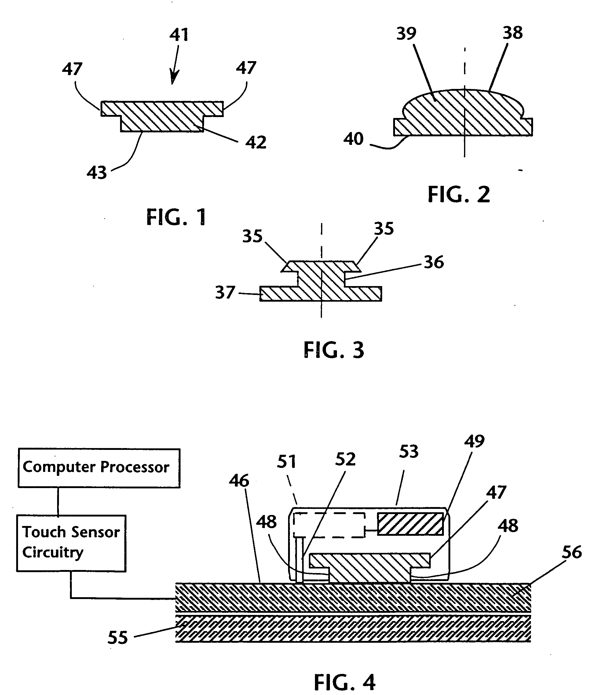
[0018]In one aspect, the invention provides a fader track that is adapted to be releasably secured to the outer surface of a touch screen device. The fader track may comprise a longitudinally extending rib adapted to be releasably secured to a touch screen device. The bottom surface of the rib may be provided with a releasable adhesive that enables temporary adhesion and many cycles of removal and placement. The rib may serve as a guide for a sliding finger touch on the top surface thereof, and the material forming the fader track may provide the lubricity that is often lacking in the touch surface of touch screen devices.
[0034]The various embodiments of the invention provide the following advantages over the prior art:
[0035]1. Much lower cost. The controller devices of the invention cost much less that existing mechanical controllers for electronic use. The embodiments designed for use with resistive touch screens have no electronics at all and are therefore very inexpensive. They are mechanical components which accomplish the equivalent of very complex and much more expensive knobs, faders and joysticks. The controllers for resistive touch screen use can cost pennies per unit to produce. The devices adapted for capacitive touch screen use incorporate only minimal electronics, and are also very inexpensive compared to comparable stand-alone controllers known in the prior art.
[0037]3. Removable devices: The controller devices of the invention (both resistive and capacitive) are removable, and may be placed on a touch screen (or cover glass) and removed many times. This aspect provides several benefits: device re-use is economical, and removable devices enable the setup of custom controller configurations in a few simple steps. Moreover, the devices may be removed at any time to clear the entire expanse of the touch screen for typical prior art touch screen functions.
[0039]5. Economy of scale: The use of software to emulate a wide range of control functions takes advantage of a microprocessor's ability to perform repetitive tasks reliably and cheaply, and obviates the need for prior art mechanical controllers that can be very expensive, require maintenance, and may be difficult to connect.

Problems solved by technology

For these inputs, a touch screen has not been well suited.
This action is difficult or awkward for many individuals, and requires that the user look at the displayed graphics in order to guide the controlling touch.
In addition, many touch screens present an outer surface that is not well suited to sliding contact; e.g., the glass or plastic outer surface may lack sufficient lubricity.
The prior art reveals a lack of devices that may be used to make inputs to a system using a touch screen.

Method used


Image

  • Touch sensor control devices
  • Touch sensor control devices
  • Touch sensor control devices

Examples


Embodiment Construction

[0073]The present invention generally provides mechanical devices to enhance the input process for touch screen devices.

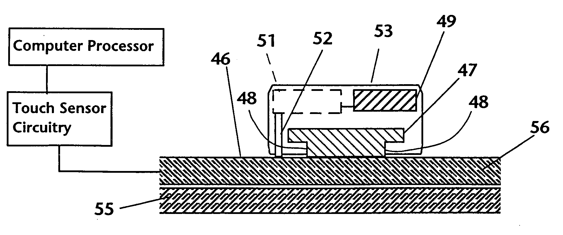
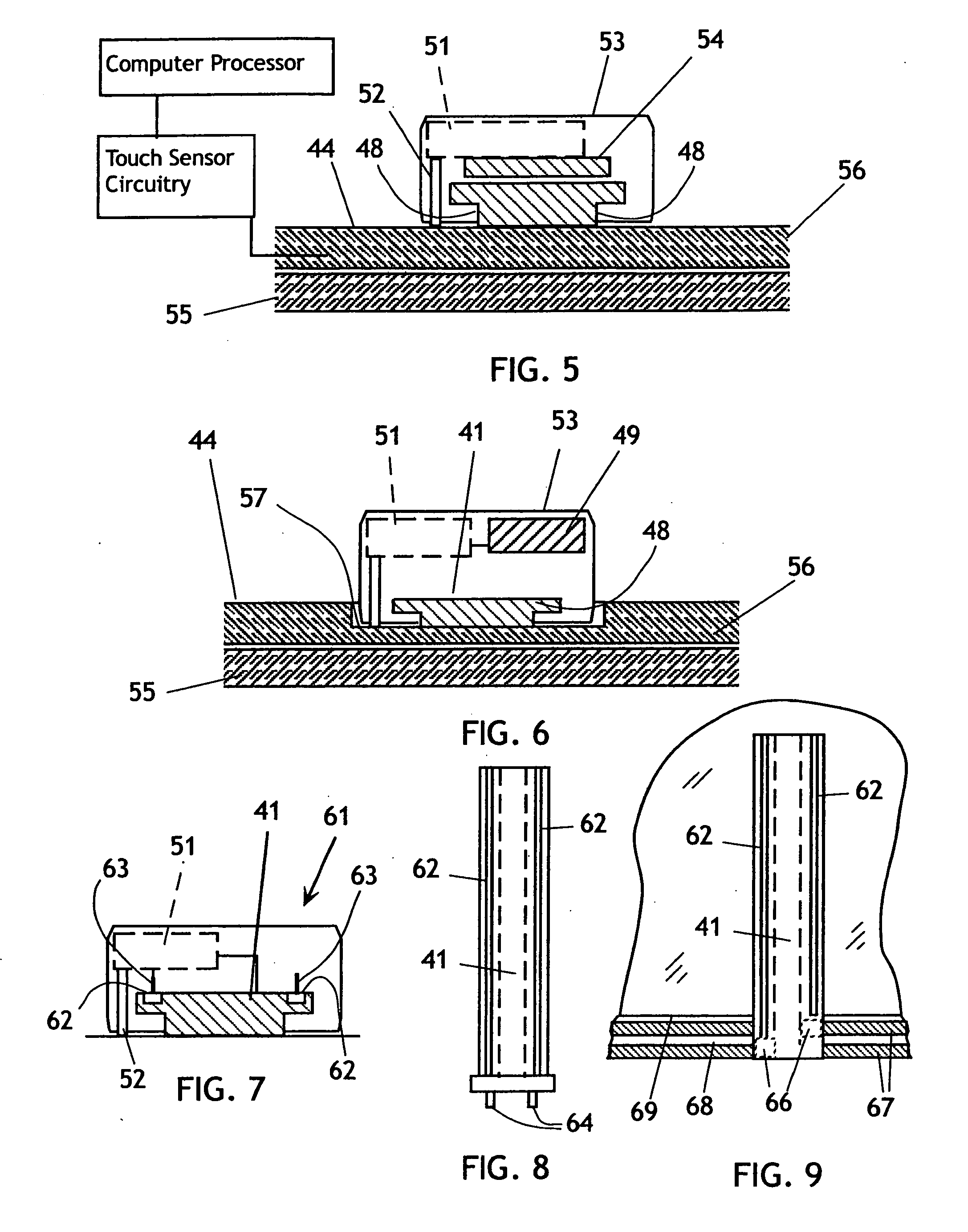
[0074]With regard to FIG. 1, one embodiment of the invention comprises a fader track controller 41 including a longitudinally extending rib 42 having a bottom surface 43 formed longitudinally therein provided with a releasable adhesive that enables temporary adhesion and many cycles of removal and placement with respect to a touch screen or its cover glass or superstrate. The rib 42 acts as a guide for a gliding finger touch to emulate the smooth longitudinal motion of a mechanical fader controller known in the prior art. The rib 42 may be formed of a lubricious plastic or polymer material that facilitates a sliding touch. The rib 42 may be placed anywhere on the touch screen surface 44, and the associated display of an electronic device may be programmed to present labeling and indicia appropriate for the desired function and range of the controller 41. The rib 42...


PUM


Abstract

The invention provides mechanical devices to enhance the input process for touch screen devices. Fader tracks with or without fader caps, rotary and fixed knobs, and joysticks may be removably adhered to a touch screen and used to emulate their respective functions, using software interpretation of the touch detections provoked by the devices to carry out the emulations. The devices are inexpensive and simple, and the touch screen and associated software provide the function and feel of electromechanical controllers that are far more expensive and difficult to connect and maintain. The devices may be provided as components on a crack-and-peel sheet. For fixed knobs, the software application accepts initial inputs and determines the location on the touch screen, and also interprets the geometry of the input strokes as commands for selected controller emulations, such as joystick, fader, knob, or mouse. The invention also provides a touch sensor controller having a longitudinal web that incorporates touch sensor electrodes and conductors and emulates a fader controller. The invention further provides a flexible track controller mounted at the periphery of a touch screen and extendable thereover to emulate a fader controller. The flexible track may be motor driven.

Description

CROSS-REFERENCE TO RELATED APPLICATIONS[0001]This application is a continuation of application Ser. No. 09 / 670,610, filed Sep. 26, 2000, for which priority is claimed.FEDERALLY SPONSORED RESEARCH[0002]Not applicable.SEQUENCE LISTING, ETC ON CD[0003]Not applicable.BACKGROUND OF THE INVENTION[0004]1. Field of the Invention[0005]This invention relates to touch screen input devices and, more particularly, to mechanical enhancements to touch screens.[0006]2. Description of Related Art[0007]Touch screen devices have become a commonplace user interface for electronic devices, computers, and the like. Touch screens are typically combined with a display screen which is in close proximity to the touch screen or which projects images through the touch screen. Under software control, the display may present images, video, alphanumeric information, and various combinations thereof. Moreover, the display may define corresponding areas of the touch screen as control input areas, through the presen...

Claims


Application Information

Patent Timeline
IPC IPC(8): G06F3/041G06F3/033G06F3/043G06F3/046
CPCG06F3/03545G06F3/0433G06F3/046G06F3/044G06F3/0338G06F3/03548G06F3/0362G06F3/0383G06F3/0393
Inventor JAEGER, DENNYTWAIN, KENNETH M.REAM, JOHN
Owner JAEGER DENNY
Learn More